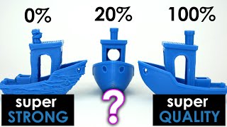
Extrusion Width - The magic parameter for strong 3D prints?

Vložit
- čas přidán 18. 10. 2019
- Start your Squarespace free trial today at www.squarespace.com/cnckitchen and use code CNCKITCHEN to get 10% off your first purchase.
Extrusion width defines how wide the lines of extruded material are. Higher values require more pressure to squeeze the molten filament out of the nozzle that also presses the layers together. I investigated how different extrusion widths impact the quality and the strength of our 3D prints and discovered that this might be a way to produce strong prints in a short amount of time.
💚 Support me 💚
Patreon: / cnckitchen
Join as a CZcams member!
Original CNC Kitchen Threaded Inserts: geni.us/CNCKInsertsChoice
Merch: teespring.com/stores/cnckitchen
Buy an Original Prusa i3 printer: geni.us/CNCKPrusa
PayPal: www.paypal.me/CNCKitchen
Shop at Matterhackers(US): www.matterhackers.com/?aff=7479
Shop at 3DJake(EU): geni.us/zHvnB
🎙Check out my PODCAST with Tom Sanladerer
/ @themeltzone
🛠Tested Materials
Spoolworks PLA: e3d-online.com/spoolworks-pla
📚Papers and further information
Slic3r Manual - Flow Math: manual.slic3r.org/advanced/fl...
⚙ My gear (Affiliate Links):
🎥 CAMERAS & LENSES
Panasonic GH5 - Professional 4k60 camera: geni.us/LMN0CmS
Panasonic GX80/GX85 - Great value system camera: geni.us/M2Sm
10-25mm f1.4 - Awesome Lense: geni.us/ZTBH
30mm f2.8 macro - Great Macro Lense: geni.us/vEwqD
12-35mm f2.6 - Great allround lense: geni.us/S9GOsr
14-140mm f3.5-5.6 - My go-to travel lense: geni.us/fSAyKo
25mm f1.4 - Nice prime for photoraphy: geni.us/mqWM
🎙AUDIO
Rode Video Mic Pro - Shotgun mic: geni.us/6JFRdJ
Rode Film Maker Kit - Wireless mic: geni.us/XMD2N
Rode NT-USB - Studio Mic: geni.us/YVONvy
🔴 LIVE STREAMING
Elgatoo Stream Deck: geni.us/ppIiAL
Elgatoo HDMI USB Capture Card: geni.us/imhD
Logitech C920 - Overhead camera: geni.us/ViVgB
🏆 Do you want to help me cover my running costs? Send me a dollar or two over PayPal, it helps me a lot!
www.paypal.me/CNCKitchen
🌼 Even watching the ads before my videos helps me a lot!
Follow me on Twitter: / cnc_kitchen
Follow me on Instagram: / cnckitchenyt
DISCLAIMER: This video was sponsored by Squarespace. - Věda a technologie


Don't forget to share this video on Facebook, Reddit, Twitter and other social media!
If you actually limited the speed to 2mm3/sec then the question is did it become stronger due to the increased layer width or the slower print speed. at 100% - .4 layer width 1mm of extruded material contains .4 * .16 = .064mm3 material so 2/.064 = 31.25 so that was printed at 31.25 mm/sec whereas the 250 * was printed at about 12.5mm/sec so the question is does the slower speed or increased layer width make a difference. Also from my experience the protocol would be to properly tune in each setting. So i would suggest this procedure
1.) establish max extrusion rate for your material and machine like indicated here grabcad.com/tutorials/dialing-in-a-filament-and-specifying-the-max-volumetric-e-xtrusion-value
2.) maybe deduct 20% to allow for the wide range of pressure difference
At this time lets assume you use PLA and 1.) established 13 mm3/sec deduct 20 % gives about 10 (lets use ten math is probably easier
3.) calc minimum speed of test which would be at 250 % which would be 10/.16 = 62.5 so 60mm/sec would be a good speed with a .4 nozzle. So in Prusa slicer the max speed and max volumetric E could be set to 60mm/sec and 10mm3/sec. With that the nozzle move speed will be constant as per my research (calling filament manufacturers) the print speed at which the nozzle moves makes a difference
4.) Dial in each extrusion width to establish a proper extrusion multiplier. to achieve similar (very close) component thickness the extrusion multiplier can vary as much as .1 (i.e .95 to 1.05) especially at the extremes. to do that I would print in your case a 1, 1,5, 2 and 3mm wall. here is a link to a print that might be useful
grabcad.com/library/frc1989-filament-dial-in-1/details?folder_id=7076739
This particular one has a 1mm. 1.25mm 1.5mm 2mm and 3mm wall. Unless you are using linear advance measure close to the middle with a caliper. This also might teach you a thing or 2 about your slicer as you can also check for horizontal layer adhesion (tip print it with .96mm layer and you can peal the 2mm wall into 2)
Then print a flat block at least 20x20 in size to inspect the surface you do not want the extrusion multiplier that high that you get a "rough ride" = have a wavy surface. Interesting different materials on the same setup in different conditions can require an extrusion multiplier as low as .9 and as high as 1.1
Now you can run your tests and should get good data on the influence of layer adhesion
Then you can re-run the test at 40, 20, 10mm/sec as max speed to see the difference the speed makes. My testing rig are my hands with which I break test pieces so not that accurate. But it seems between layer width speed plays a role too. Now i don't think it makes that much difference with a .4 nozzle but with a .8 it is much more noticable and to get good prints I usually use 110-125% for outside perimeter and 150-225 for the inside perimeters with a layer height of .4 (50%) as with a .8 a print with .4mm layer height will finish in the same time as one with a .2 due to the limiting factor being the max Volumetric E which for HIPS is about 18 mm3/sec the material we print most often and with above procedure you get not only prints strong enough but also accurate enough - look at this test
www.chiefdelphi.com/t/rack2020-test-with-updated-video/363607
That is all printed with a .8 all the yellow parts on an anycubic chiron you have 10 gears meshing and another 8 with 2 double. the bearings are also 3DP but on a prusa clone out of Nylon also with a .8 nozzle. You are looking at about 3kg of hips and 1/2kg of nylon in this video as everything is printed solid that means enough perimeters (6-16 depending on the part) to make everything a solid piece of plastic. Layer width for .88 to 1.6 on those prints.
Looking fwd to a message as to what exactly was tested a mixture of print speed and layer width or one or the other. Would like to see all of these tested so I stay tuned and a patron
LoganDark yeah we should always get these quality videos for free forever right!? Sooo weird he asks for a bit of money to do all this, but you’re right I’ll be unsubscribing to miss all the info he has just to avoid an ad. ;)
@@LoganDark4357 Have you any idea how much work goes into that - not to speak about the filaments and printer(s) etc. Just curious - how much have you contributed to his channel?
@@martinpirringer8055 Which is fine, but no need to "beg". If people feel like sharing, they will.
@@martinpirringer8055 I was told that most infills are good enough but they key to strength is a higher setting for infill and three shells minimum
The re-watchability of these videos is huge: There's so much here to try and apply!
True!!!
I keep coming back to this series everytime I have a problem, like now when I'm trying 0.5 line width to make design of parts easier 😉
I've been watching these over and over and learning loads. My first gear fix for a mixer worked right off the bat because of these videos. Nice to see a scientific analysis of the 3d printing tech.
re-watching right now
A year after I first saw this vid, here I am again...
I've had good results by setting external perimeters to 110%, and internal ones to 160%. Gives a mix of strength and details.
thanks
You should make a video where you make the ultimate strong print with all settings combined
Is there a video like that? Or not yet?
I was thinking the same then put it up against the most standard print settings
Looking at the footage of loading of the hooks I think you can reduce the data scatter if you center the load every time (with some sort of added part). It appears the load placement can change a bit from sample to sample which is going to change the bending moment in the part. Nice work by the way.
Maybe he can add small dips or ridges that hold/center the hooks in place on the part.
You are the kind of poeple who slightly change the world, thank you very much for your work. Du bist wahnsinn
I generally use 150% extrusion width for mechanical parts, although mostly it was because I print most mechanical parts with PC-CF and the larger extrusion width helps with the first layer sticking to the bed, great video!
I have been printing a lot of parts that are single wall without infill from one of 3D LabPrint's RC planes and this video helped me solve a huge problem that I have been having where the wall lines don't stick together. I didn't realize before that increasing the line thickness above the nozzle diameter was possible but I just tried it and it's turning out great now! Thank you!
You should make a video on non-printed fill material, e.g. filling the inside by injecting epoxy and other glue types. Parts come out much stronger, but there are many different options for injected infills, and also different infill percentage for printed infills.
so, molds.
@@kirbo1619 Yeah, I'd just make it out of Epoxy. Bonus for carefully mixing in some 13mm chopped glass fibre.
Just don't breathe the fibres nor leave them around nor sand/cut parts with glass/carbon fibres in them. They're an arse to work with.
This is GENIUS!!! I am SO glad CZcams exists!!! I never would've thought about filling the inside with epoxy. I actually have epoxy for the outside of some of my models though on the outside it's not for strength it's more for the finish of the product but there are some things that I make that could definitely benefit by having a boxy resin fill the inside rather than in the build
@@sub-sonicwavescaraudio1814 oh heck, I'm also thinking of using this for better transparent parts by using a clear epoxy resin.
@@forivall That is also a great idea!! I enjoy your analytical approach to problem and solution the information always useful and helpful. I have learned quite a bit from watching your content and I am definitely thankful for all your videos and teachings!!!!
Thank you for these tests, Stefan! Awesome experience!
I always set extrusion width manually for all my prints. 1st layer - keeping it as wide as practical for best bed adhesion. other layers - it depends on what I need. I always chose wide extrusion for parts that need to be strong, and you seem to have confirmed that it's a good strategy, thank you very much for specific results. And narrow for best accuracy. I actually used wide extrusion for overhangs, but your tests suggest I should pick narrow extrusion for that, so I'm gonna change that habit! Every single video of yours is like a good science paper, I love it.
I also take care to keep extrusion rate constant as much as possible, by manually computing print speed for the chosen width, layer height, and material and purpose.
Amazing, your videos really helps me with my own projects. Keep them coming!
Interesting stuff as always! I've been printing with e3d style nozzles and extrusion widths of up to ~150% nozzle diameter regularly as well ever since I forgot to do a nozzle swap at some point and noticed that things generally worked fine anyway. It's so convenient this way, as using a 0.6mm nozzle covers a huge range of usable extrusion widths and layer heights.
As for bonding strength, also consider that increasing extrusion width while holding layer height constant increases the contact surface area between layers. The cross section of an extrusion is basically a rectangle, with the sides capped by semi-circles that have a radius equal to half the layer height. These semi-circles do not touch the above and below layers. For example, assuming 0.1mm layer height (25% nozzle diameter), the percentage of each extrusion that is actually bonded to above and below layers for a 150% extrusion width is 150% - 25% = 125% nozzle diameter. And for a print done with layer height = 25% nozzle dia, and extrusion width = 100% nozzle dia, the bonded width is only 100% - 25% = 75% nozzle dia. Thus printing something with two perimeters at 150% extrusion width would result in total bonded width = 125% * 2 = 250% nozzle diameter, while doing three perimeters at 100% extrusion would result in the same wall thickness, but with a total bonded width of only 75% * 3 = 225% nozzle diameter. I wouldn't be surprised if the increase in layer bonding is more a result of the increased adhesion area than pressure effects. Practically, I dont think it really makes a difference as the general advice of using wider extrusions for stronger parts doesnt change, but it might be interesting to test if there's a difference in layer bonding between two prints done at 0.248mm layer height and 0.56mm extrusion width, one done with a 0.4mm nozzle, and one done with a 0.6mm nozzle, to try to isolate out the pressure effects.
Looks like a materal for another video
Great explanation
I really appreciate how thorough you are with the scientific process
Wasn't aware of this one, great test. Thank you.
Great to see some more systematic and scientific approaches! Thanks for your work and sharing!
Great video! Exactly the opposite of what I have been doing, I had been using smaller extrusion width settings to get better top infill on small detailed top facing parts.
That is probably a good trick for those cases, but in all others I will go with larger extrusion widths as you have shown
this is one the most usefull videos I've ever seen in 3d printing, thank u so much. Greetings from Colombia. Fahysa SAS
Great analysis. Keep up the great work.
Great video!
In Cura you can change the line width for outer wall, inner wall, infill, top and bottom, and first layer independently, also the flow for each of the previous, it's awesome!
Great channel. With high extrusion width, more heat is delivered to the spot under the nozzle orifice. Hot plastic warms the layer below, and then additional hot plastic replaces the cooler plastic.
I usually change the extrusion with along with the layer height. I mostly run a layer height of 0,3mm and an extrusion with of 0,5mm on a 0,4mm nozzle so basically 66% of layer height. I adopted these values from the default setting in cura, but scaled a bit up
Thank you Stefan. That is going to be very useful for my next project.
I've used wide extrusion width for making vase mode more successful on steeper angles in parts. I've used up to 0.8 on a 0.4 nozzle with decent results.
So what should be the initial layer line width in such a case?
When I print vase's I use an extrusion width of 1mm on a .4 nozzle, it creates a really strong print.
Rushmere3D I think that’s a 250% extrusion width
Without a doubt the best channel to improve your 3d prints.
This is good stuff Stefan. Keep it up! Thanks for all your hard work. I rly want this type of info I just don’t wanna research it myself :P
Can’t wait til you combine all the data you’ve gathered on print strength
Finally, I have been wondering about this!
Hello Stephan! I am always very impressed by your videos. My plan is to review all of your videos and make up a chart regarding parameters and strength and another all about print quality so I can use your data whatever my requirements are! I love the empirical approach that you use. If I had the time and could spare the materials I would do the same experiments but I don't have to since you are so thorough and all I have to do is fine tune your results to match my system. 3D printing is SO easy but getting very good quality and or very good strength is NOT so easy! Thank you for making the learning curve much flatter!
If this is something you're going to share out please keep me in mind!
One of the Best 3D printing channels out there!
This was very useful info for me as I am making mechanical parts and need to make hundreds of them as fast as possible at a given strength. Thanks so much for doing this. Can't wait to try this out for myself!
Yep. I've played with it. On some items that had finer details, I found the defaults in Prusa Slicer would cause some of the details (such as writing) to disappear or get muddied. I've reduced the width to a straight 0.4mm on the bottom layers where the text was and I some additional detail would be preserved.
thanks for the tip, I've noticed prusaslicer (I used superslicer but same thing) sets 0.45mm by default but never bothered changing it. I'll have to try that
Another great video Stefan.
I normally use 150% of extrusion width for infill, both for increased speed and layer adhesion. I keep perimeters between 100% and 120% for surface quality. Also use only 100% for the top-most layer for the same reason.
I also use a larger extrusion width for when I want to go with layer height bigger than nozzle diameter. Normally no less than layer height + nozzle diameter and no further than layer height + flat area of the nozzle.
Keep up the good work.
I adjust it quite frequently when trying to make large, strong parts, e.g. dust collection adapters for my woodworking tools. I'll put in a larger nozzle, typically between a 0.8 and 1.2 and adjust the extrusion width to 1.2x the nozzle diameter.
this video deserves a sub. you’ve got mine.
interesting results, thanks for sharing them.
I have just found this magic parameter in Cura and printing time from 3 hours droped to 1.5! For big prints where you dont need details definitely a good choice!
Very informative video. I use 0.7 extrusion width on my 0.6 nozzle. This seems to produce better print quality.
But after seeing this video I might have to bump it up a bit.
Keep making awesome videos like this!
Thank you for making these videos and research! :)
Great video Stefan! Wondering if an increase in Cura Extrusion Multiplier could also help strength by forcing material overlap between lines... Keep up the great work!
If it wasn’t for this channel I definitely wouldn’t be where I am now with printing, Stefan you are an inspiration and an amazing researcher!
Very revealing information thanks @CNC Kitchen good job as always
I have been playing with extrusion width (line width in cura) this last week to see if I could find one I liked better for general printing. My first goal was to see if I could save some print time by printing thicker layers with maximum width to reduce time. I've seen weaker and stronger prints because of changing it. It is really neat that this video just happened to pop up in my suggestions. I'm looking forward to watching the rest of your video at this point and see what you've discovered back in October apparently.
Once I tried to change the extrusion width to a smaller value (-5%) according to the CHEP recommendation to improve the quality of small parts.
Recently watched a video by Dmitry Sorkin, where he recommends increasing the extrusion width (up to + 200%) to get rid of zigzag movements when filling small gaps (depending on the model) and printing with fewer movements (faster than just increase print speed by same amount).
And your video with examples and science enriches my knowledge even more.
Dankeschön.
Some great info here Stephan..Thx The only thing I'd like to mention is that thinner extrusions also have more surface area per volume. This means the thinner extrusion are cooled more effectively by the fan whch makes the bonds a lot weaker. I would have liked to have seen the test done with no fan. Thx again... Thumbs up!
Very cool results! I print a lot of functional parts so this trick is perfect!
Best 3d printing channel, very very useful tests and informations
Great look at this, Thanks Stefan!
Good job! I'm already a subscriber but just clicked the notification Bell because I don't want to miss out on future videos like this.
Yep, this parameter is definitely one of the top 3 parameters I adjust in slicers. Why? Engineer. Sometimes it's because of wall feature width, and how I want the slicer to path through the section. But it's also important to maintain the aspect ratio of your extrusion path. I don't have it readily available, but some research has been done, and you don't want the aspect ratio of your extrusion line to fall below 2:1 if you care about layer bonding. Also, the internal stresses and cooling properties depend on the aspect ratio.
And you can maximize volumetric flowrate this way also. Basically, it's a super important setting :)
Once again, fascinating and very useful to some printing I'm doing right now!
thanks for making this big effort and scientific tests. They are very usefull
This is great. Looks like 150% might be the magic number. Would be nice to see the hooks tested at 150% and 2 or 3 layers. I don't imagine many people will prefer to use 200% due to the surface quality.
very very helpful thank you
Danke für diese hochprofessionellen Videos! :) Taugt mir voll!
Gerne!
I like these instructions.
Thanks for the heads-up! I never touched extrusion widthexcept for dialling in exact dimensions on the finished part, which has been superseded by XY compensation built-in to the slicer.
Great video. There are so many parameters to obtain the best results.
I use Slic3r and I have always set the extrusion widths manually. First layer is tuned to provide the best fit for the geometry of that layer--wider being preferred as the squashing bonds to the bed better and because it makes a better looking surface finish. Other layers are set for similar reasons. This video surprised me as I thought everyone did this.
7:05 thank you for your hard work, excellent science!
I hardly comment on stuff so when I do I feel it really good or really bad. This one is really good. Very good information, show visual results, shows textual results, very well thought out and laid out. A lot of good information in a relative short time, no "jibber jabber". What would be nice to see is a comparison on infill compression strength (and other related tests). Take for example you need to created a special part for something that is not longer available, too long to get, or expensive. What would one have as options with 3D prints. For example, maybe a busing / spacer or heavy equipment floor foot or a dampener made of ABS vs. PLA. vs. PETG vs. TPU. Any what happens at different fill patterns and fill percentage. What about lower fill percentage but different pattern and/or different infill line multipliers. What about general line width and height. And document (print) time and cost (material + power). As a hobbyist, I'm usually more concerned with lower time and cost. However, sometimes quality is more important. This probably could be split up in two (or more) parts. A) Infill compression strength B) General compression strength (ie. same infill parameters but different wall counts, layer height, etc. I did see the Gradient infill video also, more good information.
I've used it for the 1st layer to improve bed adhesion when printing directly on glass of heated bed. No glue, hair spray or any other material needed to get items to stick to the glass.
U da goat in tha hood
I've only ever played with the extrusion width when doing vase mode prints... 0.8 line width turns out GREAT but I have to bump up the heat and slow down the print a bit. I use these prints as pencil/tool holders :P
I have always ran my Line width .04mm smaller than what my nozzle actually is.
I use a .6mm nozzle, and running a .56mm line width always gives me amazing results, i've actually figured this was one of the most important settings for the quality of prints I produce.
I find even just the direction of the layers can play a huge role in strength. I often have to move models around to get usable prints
Obsessively brilliant work as usual. Thanks ;-)
A arrived at at an extrusion width of 120% this way: I had over-extrusion; stringing, and bumpy walls. Testing showed walls became smooth at a multiplier .87. But now there were gaps on the top and bottom infill. Adjusting the extrusion width to 120% made the tops of my parts perfectly smooth. My settings are very far from normal, but my parts a practically flawless, and strong with this material
120% (.48) is the stock setting in Simplified3D
Thanks for this.
I've been playing with extrusion width doing vase mode prints, notably getting better looking results with a 0.6 nozzle at 0.2mm layer height and a maximum of 1.1mm width rather than going to a wider nozzle. And with all the nozzles I have the sold part of the tip is the same width so I can't push the width beyond 110% with a 1mm nozzle, but obvs I can go with taller layers for speed, but getting crazy overhangs on vases needs low layer heights.
Really great work, thank you.
I experimented with extrusion width for several weeks, because I had problems with overhangs curling upwards.
In the end is was a problem created by several factors and not just one - but the width of extrusion had to do with it and by changing it to a certain percentage of the layer height I was able to increase print quality significantly.
My hotend always bumped into the upwards curling layers on little structures like the leapfrogs front arms...
Could not print that darn frog without layershift for that reason for almost a month.
Was tweeking it like crazy.
Cooling, extrusion width and a slightly dented nozzle which was set up a tiny Bit off of a 90 degree angle and it's tip scratched the surface of the extruded plastic like scissors do on Christmas wrapping when you want it to curl!
Took me forever to figure out.
I print with wet nylon so I do tweak the extrusion width a lot. I have to tweak pretty much everything to get perfect prints with it
Yesterday after the first testing runs with the Titan Aero volcano I changed the S3D First layer height and width from std. 50% to 150% and first layer was 150% better. I guess this is also a bit like the extrusion width setting. Nice video!
I have changed my extrusion width to 0.5mm when using a 0.4mm nozzle a few times to speed up printing of thin walls.
A lot of designs are made with solid wall thicknesses of 1-2mm which is an obvious consequence of designing in terms of 1mm units to keep the design math simple. However if you print a solid wall of 1mm thickness with a 0.4mm nozzle you will get a straight outer wall on each side and a 0.2mm gap in the middle which gets printed with the fill pattern. This slows down the overall print a lot. If you adjust the extrusion width to 0.5mm then you get a straight line on both sides with no infill required.
However I have also found that doing this reduces layer adhesion and makes such walls more fragile. But depending on your end use goals the tradeoff in strength may be worth the significant reduction in print time.
I have changed extrusion width quite a few times. It can help increase printable angle in vase mode since the line gets wider relative to the offset given the height (there are limitations of course). I have gotten 30 degrees included angles to build plate with polypropylene to print no problem for clear vase type parts. I have also used it many times for lower detail parts to increase speed or beef up wall thickness where I don’t want to wait for an extra perimeters. Sometimes you get better detail with shorter layer heights and wider lines. Just depends. It’s another tool in the toolbox.
Another great video! I've been waiting for this one, it goes along with what I have observed, but it's great seeing it confirmed systematically. I have a 3D Printing presentation coming up with quite a few other engineers maybe 100-200 I'll be sure to reference your channel 😉
Hi Garrett, please have a look at my recent publication systematically varying width and height for five different values. I hope it'll be interesting for you if you like this video. www.researchgate.net/publication/341289167_Interlayer_bonding_has_bulk-material_strength_in_extrusion_additive_manufacturing_new_understanding_of_anisotropy
Very useful and well presentation information. Thanks!
Been testing case mode for the first time recently. Increasing line width can be good sometimes
This is exactly the kinds of tests I've been looking for. I'm currently planning to buy a printer and want to build a mount for my computer monitors so strenght is important.
Best 3D printing channel on CZcams!
I use a 0.8mm nozzle and print at 1.0mm layer width. In vase mode the prints are surprisingly tough, far tougher than I originally expected. To allow enough time for heating, I keep my speeds down to around 40 or 50 mm/s, this also helps to increase layer adhesion.
very clear answer!! Thanks dude!😉👍
I do this on basically every print I print. It was nice to know that layer adhesion increased that much and that two lines was best using the same overall wall thickness.
Using Cura, I set the outer wall line width close to 0.4mm to maintain horizontal resolution. I then increase Inner wall line width, infill line width and top/bottom line width up to 0.8mm. I have not seen the rough surfaces that you got here, perhaps that's a result of not printing hot enough. Increasing infill line width allows you to print it with higher speed without the lines being cut off when it crosses an already printed infill line.
Lastly, I reduce top surface line with to 0.3 or 0.35 to get a smoother top surface layer. This is a good alternative to Ironing which takes a lot more time, although this doesn't get as smooth. I do this even when I use ironing to give the ironing a smoother base to work on.
Another thing that I have been meaning to test is if wider line width also allows higher layer height and how that compares to using a larger nozzle.
Amazing scientific level work
I frequently use a 0.3mm extrusion width for external perimeters and top solid infill in order to create higher detail on the top surface when printing with a 0.4mm nozzle. I use this for embossing text or logos on top of models.
I whould like a overall tutorial on how to get stronger prints 😊.
I would find it interesting to test various dips, solvent bathes and injection. For ABS I suspect you could dissolve some ABS in a solvent until it gains some viscosity, then drop your part in, vacuum the air out, and quickly take your part out. It might require a quick swish in just the solvent to clean the outside off.
Another thing that would be interesting is if there were a fill pattern that changed with the distance from the wall. You could have the density high close to the wall, and low in the middle of the parts. Likely achieving the same strength as a higher fill density, but with faster print times and lower material usage.
I have also thought that the nozzle tip diameter (not the oriface) has an effect on strength. That it might preheat the previous layer slightly, and definitely an adjacent line on the current layer, by rubbing across it. So perhaps a larger diameter would improve the pre melting. Even better would be a laser that tracks in front of the current line, preheating just the small area the width of the printing line to nearly its melting point. Obviously this would be a significant design challange.
one cool idea i had that actually has been tried is making holes in your parts. maybe you should also check stuff that can affect the print strength that aren't just in the settings some people mentioned adding small hollow cylinders inside the part to force shells inside the part. but my idea was different. I wanted to make holes in the infill then after it's about to close I'd tell the nozzle to go into the hole, lower a little depending on the nozzle shape and maybe with a high temp extruder a tone of material until it fills the hole. this is perfectly fused material without layers inside so it'll greatly increase the z strength in theory! with a tool changer you could even inject resin into that hole :)
Hey Stephan! Paused at 1:18. I've been off-and-on 3D printing for 6 years now, and extrusion width issomething I've always tweaked with my prints. I use S3D, and it's always front and center on the first page of the settings, so it was one of the first things I messed with once I started tweaking advanced settings. Usually I will leave it on Auto or .4mm to start, then once I preview the print and time, I will adjust as necessary. If I'm printing something large, I will usually bump it up a bit, and it will equate to big time saves. If I'm printing something small and detailed, or with thin walls, I will often lower the width in order allow the printer to use solid lines rather than a perimeter with tiny zig-zag infill. Very thin infill usually equates to tons of vibration, so I usually make it my goal to adjust the line thickness and number of permiters (coupled with the "single extrusion perimeter overlap" setting on the last page) in order to get a single solid line of infil.
I also HEAVILY lower the thickness (and speed) when I'm printing very tiny parts. I know I could use a smaller nozzle, but sometimes that's a big pain for just a single small print. I once printed a very tiny lightning bolt, something like 12mm in length, 3mm wide, 5mm thick. I used a .05 layer thickness, a line width of .2mm, and a speed of like 5mm/sec. It was smaller than my fingernail, and still took like 12 or 15 minutes to print, but came out great! It took a handful of attempts to dial it in, but there was no way I could get the detail and sharp corners in a piece like that without lowering the width of the line! (:
Ive cranked up the extrusion width on a lot of big mechanical parts, just to throw down more plastic faster (didn't realize it was stronger). Ive also cranked down the extrusion width for the infill occasionally (which is a simplified 3d option), since that will increase the number of infill "boxes", which is useful when i need more internal infill support for the top layers, but dont want to increase the overall weight
with flexible filaments i use a combination of this, linear advance, and over extrusion to get solid, clean parts. for example i might print fiberlogy fiberflex 40d at .4 nozzle .36 extrusion 1.25 extrusion multiplier, and using linear advance and the perimeter overlap ect to get the cleanest top surface. works pretty well!
Your awesome! If I just watch you channel, so many of my questions will get answered.
Glad to hear it!
Awesome and super informative video, danke!
U r a legend my guy
Awesome work. Appreciate it
I use 0.6mm with a 0.4nozzle as standard for functional prints just for speed. I thought they we stronger to but this test proves it :) I adjust the width to get optimal lines for thinner parts and that varies a lot, from 0.34 to 0.75 and I haven't seen much issues
Gutes Video! Weiter so Stefan!
Changing the extrusion width was useful to vary the stiffness of parts printed with flexible filaments. I found that perimeters of 1 or 2 layers can be very strong when extrusion width is around 0.6mm (w/ 0.4mm nozzle)
i mainly change the extrusion width when printing vases, makes the single wall a bit thicker and stronger withouit me needing to go through the hassle of swappign nozzles.
Stefan, I set my profiles to 150% for perimeter width / infill width, and use 125% for external perimeters and top infill. There are a few cases when I do 200%: for most of my ABS prints and all of my PC prints. I've had such success with this that I don't even use ABS anymore, I just use PC when I need a higher temp or higher strength material. In those cases I also use a lower layer height.
I set up a CR10 s5 with a volcano nozzle per your old CR10 TitanAero/Volcano video, on that I run a 0.8 nozzle, 0.4 layers with 1.2 extrusion width and it is incredible. Sometimes I turn the layer height and width down a bit for better looking or non-structural parts, but the 1.2mm wall thickness (per perimeter) makes for strong, fast parts. (I only print PLA on the CR10).
Yeah, I've modified it when printing vase mode to beef up the print.
Did this for vase mode lightsaber parts, resulted in a much stronger "blade".