LM317 Current Boosting Circuits [2N3055, MJ2955]

Vložit
- čas přidán 10. 03. 2020
- LM317 Current Boost Circuits using 2N3055 and MJ2955
======================================
Altium Designer + License (Free): www.altium.com/yt/myvanitar
======================================
Article Source (Schematic, Details): www.pcbway.com/blog/technolog...
======================================
Check other videos: bit.ly/2N9OlPa
======================================
#LM317
LM317 is one of the most popular adjustable regulator chips. The output voltage of the regulator can be adjusted from 1.25V to 35V. However, the chip can deliver currents up to 1.5A which is not enough for some power applications. In this article, I will discuss two methods of LM317 current boosting, using power PNP and NPN pass transistors.
According to the LM317 datasheet: “The LM317 [1, 2] device is an adjustable three-terminal positive-voltage regulator capable of supplying more than 1.5 A over an output-voltage range of 1.25 V to 37 V. It requires only two external resistors to set the output voltage. The device features a typical line regulation of 0.01% and a typical load regulation of 0.1%. It includes current limiting, thermal overload protection, and safe operating area protection. Overload protection remains functional even if the ADJUST terminal is disconnected.”
This information proves to us that this cheap 3-terminal device is suitable for many applications but it comes with a drawback for power applications and that is the limitation of the regulator’s output current handling (1.5A in the best conditions). This problem can be solved using a pass power transistor.
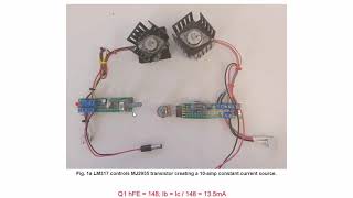
Current Boosting Using a PNP Power Transistor (MJ2955)
Figure-1 shows the schematic diagram of the circuit. This is an adjustable high current regulator circuit that the output voltage can be adjusted using a 5K potentiometer.
The 10R resistor defines the Turn-On time of the pass-transistor and by the way, it defines how much current should passe through the LM317 and MJ2955 [3, 4]. Based on this parameter, the power rate of the resistor must be calculated. 1N4007 is a protective diode and 270R resistor provides the necessary ADJ pin’s current. As mentioned earlier, the 5K potentiometer defines the output voltage. 1000uF, 10uF, and 100nF capacitors have used to reduce noises. Don’t forget to install the transistor on a big heatsink.
[A-2] Current Boosting Using an NPN Power Transistor (2N3055)
Figure-2 shows the schematic diagram of the circuit. The 10K resistor at the output draws a small amount of current to avoid the floating output and it helps to stabilize the output voltage. Here 2N3055 [5, 6] plays the role of pass-transistor also. - Věda a technologie


LM317 is one of the most popular adjustable regulator chips. The output voltage of the regulator can be adjusted from 1.25V to 35V. However, the chip can deliver currents up to 1.5A which is not enough for some power applications. In this video/article, I will discuss two methods of LM317 current boosting, using power PNP and NPN pass transistors.
Great
czcams.com/video/3ZMfVpUieFc/video.html
Or just use an LM338 with a good heatsink and forget the pass transistor.
The forum and the schematics was very helpful thank you so much
Glad it helped
Excellent video. Thank you !
You are welcome!
good one!
Hello from India....Thank you very much Sir for this easy to understand and very helpful video. Subscibed for more.
The Maximum Amp draw per gauge of wire Chart, shows that the breadboard kit wire at 24 gauge can only handle 1.154 Amps, which supports the 5 Watt or less theory
that's for testing to show the proof of concept. in practice, you're gonna design a PCB
As you can see it can handle little bit more for couple seconds... before it will meltdown :D
داداش خسته نباشی
Hello very great-clever idea.,
I have a question for your current boost by a 2N3055,
in my old circuit power supply 0-25V - 1.5 A, with 2 x LM 317s,
the first Lm317 works as current limiter & from his output the DC voltage
goes to the second LM 317 for voltage adjust 0 to 25 V for output terminal,
does the right conect the transistor 2N3055 to the first LM 317(current limiter)?
and the resistor's pin 10KΩ connect to this LM's out OR to output terminals + & - ?? or not..
(Iam a simple amateur)
Thank you
*I tryed to upload here a schematic by google-drive (to see you what I mean)
but doesn't let me to upload the link here
No need to upload the schematic, I got what you mean. Truly, I have not tested your configuration myself but I think your assumption is right. However, I think you should try the PNP solution. Just try on a breadboard. shouldn't be difficult
@@MyVanitar ,
Thank you very much for your fast reply,
I asked about 2N3055 mod. because I have many spares of them .
What is your opinion,
for where I will connect the end of the 10K resistor;
At the output of the first current limiter LM 317"or at the output terminal
(if something does not work, I will try with a MJ 2955)
thanks again
The 10K res just provide a minimum load to keep the output stable. so I think you should use it for the second stage (voltage regulator)
@@MyVanitar ,
hello ,
finally i replaced both the Lm317s by lm350t
(because the transformer its up to 3A total)
the circuit works fine+output protection up to 3A without other mod.
thnX for help
@@Ianistrip good luck
👏👏👏
Good job experience mate
Thanks 👍
I have 18V 30A transformer. Can I use MJ11032 instead of 2N3055 and possibly replace LM317 with LM350 if need be?
How much current you want to get at the output?
@@MyVanitar All 30 amps considering MJ11032 can handle 50 amps easily. They should be heatsinked of course anyways.
@@ruslank4028 You can not get 30A out of a 30A transformer. also you must consider dissipation and voltage drops. I suggest you to use an SMPS. switching power supply
Hello, thanks for project. i have some trouble with this schematic potentiometer. When i reach minimum potentiometer is burning. İn schematic potentiometer 5k or with 5k serial resistor ? its my school project and i stuck.. in the output so unregulated i think potentiometer cause that too.
My 270r resistor is old maybe i should change that.. any suggest ?
man schematic is very easy, why you should have any problem. if you do not have a 5K pot, use 10K
Nice
Thanks
Can i use a 25c1106 npn power transistor?
don't worry, just try
@@MyVanitar alright thanks 🙏
Show us the wiring diagram please
It's a good practice that you invest time and not be hurry, I have mentioned where you can find more info
Can i use tip3055?
yes
Plise make a video LM317 and 13005 from old cfl lamp to boost the current pliz 🙏🙏🙏🙏
I have (15) 13003
And (5) 13005
You can not make a test yourself? It's not a complex circuit. if yes, what results you got?
It not working but why????
All connection was right 😞
Tell me pliz
@@Electronic_For_You How exactly not working? You don't have an output voltage or what? Please recheck although this is a switching transistor
Great job bro, i want a circuit diagram please.
Check description
Is it possible to make the same circuit for LM337 in negative voltage? For a dual power supply.
Good question, I have not seen a reference design for this, but I think if you use the second circuit and replace 2N3055 with MJ2955 for LM337, it should work, but I have not tested it
میگم ی مدار حفاظت اتصال کوتاه سراغ نداری؟ بدون رله
Not now, but I'll consider it for future projects. Please only write English comment to be useful for others also
@@MyVanitar ok tnx for replay also when u make a new video for that short circut? with out relay
MJE 3055 will work same????
try it. it will work but I am not sure about heat dissipation or current delivery, but its DC current gain rate is good
I have old 13005 they are not working same why????
2n3055 can i use 2 of them????
For 8A ??????
@@Electronic_For_You Theoretically Yes, but I have not tested it myself. You can not simply parallel them. Do some research. if I gonna answer this, it takes another video
@@Electronic_For_You How they work?
Thanks for the video. I read your article. You are kind to share this info. Im looking to build a variable dc power (0-48v) supply with 15 to 20 amp current output. a microwave transformer 220v input to 12v output with KBPC 5010 FBR and beafy cap. I dont know how to calculate the capacitor rating that i need though. Then this circuit of your design afterwards with digital V and A readout. Going to need cooling fan also and safety fuse. Im subscribed and you need more subs and likes. Any tips and advice from your side wil be much appreciated. ( im new to electronics by the way, need to learn allot more)
Thanks, Johan. if I understood you correctly, you wanna build a 0-50V supply that can handle up to 20A. You decided to use a 12V microwave transformer. There are two problems, I don't think your selected transformer is a good choice since the output is 12V and I don't think it can handle such a current, because the circuit will have some drops and dissipation as well. The easiest method for you (because you said you are new and you wanna learn staff) is to use a commercial SMPS (the ones with metal case) with at least 50V output and 20A. then connect the output of this SMPS to a powerful DC to DC Buck converter module to be able to adjust the V and A. You may be able to find a commercial unit for your purpose, I can introduce the Siglent new power supplies with digital display. Linear power supplies are good for sensitive devices and laboratory equipment. for power applications, SMPS (switching power supplies) are far more efficient. a 20A transformer is huge and quite heavy!
There's a circuit on Circuit Exchange International using the LM 317 regulator with 5 or 6 TIP 2995 transistors to boost the current. Built into an old pc tower case. The transformer and heatsink are large and a dissipation of around 40W or higher is stated. Use the HVT version of the regulator to provide 48v limiting the current to around 660mA to 700mA by a resistor on the input of the regulator. Use the voltage drop across this resistor to operate the boost transistors. There's a circuit on the Texas Instruments datasheet that uses a PNP driver transistor with NPN pass transistors in conjunction with the LM317 regulator.
Where to buy that circuit?
I have not designed a PCB for this because the circuit was simple, just follow one of the schematics you like
@@MyVanitar I made John hutchison crystal cells I got 10 volt very steady but low amperage....don't know what boost converter suits my application
these are linear power supplies or linear regulators (with current boosters), I have introduced a boost converter in another video
@@MyVanitar thank u Brother only u replied...no one wants to contribute...
You are losing voltage in the small lead wires you are using. The LM317 can regulate far better than you demonstrated. The voltage drop on your lead wires must be huge. Good video for newbies. Adding a pass transistor for more current is far cheaper than buying LM338 if you need more than 1.5 amps.
Do you think I don't know that?! This is just for testing, you have to design your PCB if you would like to use this circuit seriously. Yes LM338 is expensive and its thermal dissipation is not as good as a power transistor
@@MyVanitar I know you knew that. I put it out there for the newbies since you didn't mention it in your video. Croc/Aligator leads today are so cheap and tiny gauge they are only good for a few milliamp loads.
Yes, I have made some of those Alligators for myself using a good thick copper wire. Thank you for your comment. actually, most people don't watch the content completely and that makes the difference between a wise person like you and a person who just makes arguments about anything. another example is my last video (fake soldering iron). People see their 40W soldering irons are unable to melt a simple thing, especially with flux and another 40W iron does easily, but just argue with me that power measurement is irrelevant
@@MyVanitar Absolutely. I make leads with 14 gauge wire I have from stripped line cords from appliances for some testing I do. It amazes me that the clips today aren't even soldered. They just use the strain relief crimps to bond the wire to the clip.
Diagram please.........
Check the video description
You have to click "MORE" in the description because there's a ======================= line
Where is the circuit diagram ?
Please watch the video completely, when you are hurry, you can not learn something correctly.
@@MyVanitar I watched the complete video but couldn't find the circuit of current booster you said in description with npn & pnp transistor
@@amitghosh6966 Check the video description, there is a link to the article
Diagram please.........
Check the video description
@@MyVanitar Thanks, more power supply topics please.......
@@gerryboypanot7344 I have more designs also, check my other videos