Video není dostupné.
Omlouváme se.
LM317: How To Increase Amperage (Ep. 3)

Vložit
- čas přidán 26. 07. 2024
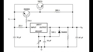
- I build on last weeks circuit and demonstrate how to allow more current to flow through an LM317 voltage regulator circuit.
My Multimeter: amzn.to/3gjOACw
My Soldering Mat: amzn.to/3aM1qIy
----------------------TABLE OF CONTENTS----------------------
Intro - 0:00
Theory - 1:16
Building - 20:46
Demonstration - 26:12
Conclusion - 29:38
----------------------------------------------------------------------------------
This is the third installment of my electronics tutorials, so be sure go go back and watch the previous videos if you haven't already.
Previous Episode - • LM317: How It Works an...

![LM317 Current Boosting Circuits [2N3055, MJ2955]](http://i.ytimg.com/vi/FItAwcsj0OI/mqdefault.jpg)


best explanation of BJT that I've seen so far. Now it makes much more sense.
Your the first person to make since about electronics to me.. Thank you Jake.
Im glad i could help bring you clarity on the subject. I also had a hard time learning, and is why i made my tutorials.
Good video, thank you for making it. One caution, for clarity... As the current is not automatically limited by the circuit, the voltage must be limited manually (via the pot) such that the total wattage output of the circuit does not exceed the wattage limit of the power transistor(s). Otherwise, the power transistors will burn up. Meaning, the number of transistors needed is based on the wattage limit of the transistors, not their maximum current output ability.
Great sharing of principle of pwrBypass circuit :) ..Though, change little bit and put those 1ohm balancing-resistor on emitter-pins side(instead of the collector side). This more effectively help to equalize the base-emitter junction, and thereby the load-sharing between those two transistors (same principle often used on audio OutputPowerStage in amplifiers with parallel transistors). Search the net for 'emitter-resistors', one can find lot of good explanation on it. //Still thank you for sharing Jake. Electronic = one of the best hobbies :-)
Watch this first video and subscribed
Thank you for taking time and explaining the microscopic life of this circuit.
Thanks well explained. Cleared my mistry
If you put a pot on the lower bjt of the darlington pair , you can have adjustable amps.also you need heat sinks on them.also for the voltage protection, the way you have it yes it will work but the diode will usually be burnt. If you make it so the volts are terminated at the base of the lower bjt with a relay ,the circuit will still deactivate the current and will not blow your diodes. If you want I can send you the schematic. But we’ll done man , great job.
Holy crap, why are you even watching this then? LOL
In seriousness, youre probably right. This was just a basic demo to fill a gap of knowledge on youtube. It was hard for me to understand the logic of this circuit and circuits like this, so i studied hard and made this vid.
Thanks for the feedback, and in the future i may make a more complex demo with some of what you described.
@@JakeSublime lol. I’m not a genius either bud. Just getting back into it lol. But you gave a great demo , you gonna do great bud.
@@JakeSublime make an updaTE VERSION
Great video thanks for sharing. Some things to note. Use fireproof wire wound cement resistors 2 or 3 watt or hired depending on the voltage you are using the resistors get hot they can burn up or even catch on fire. And always make sure to use a heat sink with a Mica insulator sheet with thermal paste applied to the back of the regulator to help dissipate the heat from the regulator. Regulators get hot and can burn up. And also use thermal paste and heat sink that diode the diode will get hot and burn up as well. And also apply thermal paste to the transistors and heat sink them also because they get hot heat will destroy the circuit if not properly cooled using a small fan can help also. Just trying to help 🤗 And as far as transistors go I would use the BF423 PNP transistor if you are going to use a small TO-92 package transistor or the 2SA949, 2SA988. And you can also use the mje350,mje15033 or MOSFETs IRF9642,IRFP640,IRFP940 as well look at all the data sheets for each one of these and you'll see why.
diode doesn't need heatsink it's not doing any work.
@@purebloodsunite7489 diodes get hot and they need to be cooled. I build amplifiers and also repair them And when you're dealing with voltage there is heat dissipation and it can get hot especially if you are using high current/ voltage. And diodes can be used as a regulator as well and they do get hot under certain conditions. Do your research many blessings
@@purebloodsunite7489 Using a Zener diode is not usually a great way to produce a regulated output voltage because it leads to excessive current consumption and heating. But if you do, it might be better to use, say, a 3.9V Zener, and then an emitter follower to supply current to the ESP8266.
- user57037
Oct 17, 2018 at 5:22 this is an article I found online for you this is only a example therefore that zener diode needs a heatsink with heat sink paste because it gets hot and can burn up especially if you're using hight voltage
@@purebloodsunite7489 I was working on a Sony amplifier and the voltage regulator was getting to hot they used 6x33 ohm cement resistors and a 15 volt regulator they were using a 37volt Dc power supply the regulator was getting 24volts at the input of the regulator 22volts dc is Max for this regulator that was being use in this amplifier because of the size of the heatsink they were using for the regulator was to small! But anyways I use a 24-volt zener diode between the 6x33 ohm cement resistors down to ground and the zener diode did get hot. But the amplifier is working fine now. And yes all the cement resistors are getting hot as well it's the way they chose to build this amplifier and in case you don't believe me use a +37 volts DC power supply a 15 volt regulator 6 x 33 ohm 2w cement resistors stacked in a row of 3 and a 24v zener diode between the second row of the 33 ohm resistors down to ground use the Motorola 1N5359B 24 volt 4A silicon zener diode only not a glass zener you can find this diode on eBay 3 for $6.13 and if you do it right you should see about +22v DC on the input of the regulator and tell me if it don't get hot😂
One of the best tutorial.
Thanks a bunch :)
Its why i made the video! :)
a very good video,Thank you
Well I think you did a real good job of explaining how to get more amperage. But this world today, when they say high amperage people think of
3 - 10 amps is high that's nothing but small amps it can't even run my ham radio.
High amperage which is
40amps and Above!
What I have noticed on other CZcams channels when you ask to show, how to get more current then they show you volts, so they let me know that they're confused and they have not went to school yet. because in electronic class current and amperage are the same, so I try to stay away from those kind of Channels
thank you bros GOD bless you
Im very glad i could help you. :)
Hello! This is probably the best explanation i see on this topic so far! But still i don't get the principle of voltage equalization between collector and output. Could you please explain how that happens?
Hey great video! I just have a question... I know that you can use the LM317 as a constant current source if you hook it up differently. However if you want high current then the current sense resistor will dissipate a lot of power. Can this be used to have less current pass through the resistors too?
Great video tutorial !!!, it could be nice if you explain here that you are using the conventional current flow instead of the electron current flow, THANKS ⭐⭐⭐⭐⭐
Hi
Sorry, but I dont understand. What controlls the voltage comming from the tip32, so it dosent send out the same voltage as it gets in? I mean, if the 317 is adjusted to an output of 15v and the bjt get 20v in, what prevents it from sending out the full 20v... I cant figure out how it is controlled😚
Kind regards
Claus
Did you got the reason why it’s still regulated on the output? I tested it and it works even on higher current, I just don’t get why it works, shouldn’t the on transistor act like a “path of least resistance”? I don’t get why it still gets regulated…
Small streams may join together to form rivers. All rivers eventually lead to the ocean or lakes.
Hi, thank You for video. Is it possible to make the circuit to negative voltage, with LM337?
Yes you can but use the complementary transistors to the ones in the article. One boosting current method is to add an extra driver transistor before the regulator. PNP for positive polarity, NPN for the negative polarity (this method may be shown on the datasheets as an alternative boosting circuit but is mainly used if a fixed maximum current rating is required). Extra pass transistors can be used with the appropriate current share resistors 5W to 10W rated.
HELLO SIR! YOU DESERVE MORE SUBSCRIBE!
LOL YES but i will split my channel into cars and electronics soon, so you wont get blasted with car stuff when you subbed for electronics.
@@JakeSublime very good idea sir! Keep it up :)
thanks a million Jakes .Plz i want to know if this circuit can be used as a boost battery charger for fast charging
This is simply a voltage regulating circuit. With a fuse in line of the output (To ensure you dont go over the designed amperage) , you could theoretically drive anything you want with it.
How can i increase current on a 3phase wind generator that converts to 12-16v but at about 1amp? Need more amps to charge batteries. Cheers
Lm317, 350 & 338 in To-220 package can't handle more current if power dissipation goes upto 25 watts or so while the To-3 package of Lm350 & 338 may handle upto 25 watts with a big heatsink if we're making a variable power supply upto 18 volts & 2 amps because at lower output voltage with higher current have higher power dissipation
is it posable to use mosfet irfz 44 n
What transistor is that? And what transformer did you used. Can i you my 12 0 12, 1 amp transformer here? Thankyou
14:02
I've built nearly same circuit with lm317 only but giving me onle few ma. It is said that it can give 1.5amp most why is this?
Thks.
Its possible you wired something incorrectly. It happens to the best of us. Have you watched the series from the beginning? I suggest tearing your circuit down and rewiring it.
Also, what are you trying to power with this circuit?
Hi Jacob thks for response. My circuit without 2n3055's but still is said that it should give over 1amp. Pots to adj have to be big? Cause mine are 1/4 w. Thks.
Hey Jacob thank you for the explanation of the circuit. Its very usefull for me that im just starting with this. What should i change for 20A?
The transistors i used to increase the amperage over the LM317 arent particularly unique, you can use another transistor thats the same doping type but that has a higher amperage rating.
I suggest going to your favorite online electronics supply and searching for a higher amperage rated transistor. The circuit should work the same, so long as the upgraded transistor is of the same doping as mentioned in the video.
@@jakecastle4426 do you know if i can use the irlz44n?
@@focametal thats a mosfet not a BJT so you would have to redesign the whole circuit if you wanted to use it
I build unregulated 400 Amp power supplies. I feel like your the man to talk to about helping design a voltage regulator for that circuit. I run 13 volts upwards of 16 volts. I need a solid regulator design that I cna build myself. I know they use something like this but I wanna know it's correct. If you can help me out I will credit you in my builds till the end of time. I'd seriously appreciate it
Also fantastic job on explaining this. Best video I've seen yet by a LONG shot.
So, could we just cut this short by using a lm2675?
If the external issue of that linear then you remove the input resistor to increase current.
The internal limit, replace the IC.
Supply issue. Run dual (or more) circuits. (Same voltage double the current)
Just saying
I would if agreed as of a few days ago and its funny you mentioned it in this video no not all rivers named a river starts or ends in the ocean i just followed a local river and it runs in circles
Uhhh lol wut?
@@JakeSublime a river by my house it runs around in circles
Wich alternative than lm317 with less voltage drop out?thanks
The LD1083 to LD1086 series of voltage regulators.
What is the use of this video. It is for a high amps with a lm317t and then you test is at 300ma. which is way less than the lm317t. Now about the 1 ohm resistors you give no wattage for them, do they have to be to suit the load say 100 watt for 10 v at 10 Amps.
I was taught that as the current increases thru a resistor the voltage across it increases, that is I x R
Amazing video! one thing I don't understand is the transistor (that the entire crutch of the video but hey)
IF you supply a unregulated voltage into the circuit and the transistor opens, wouldn't the electricity going on the load be unregulated because it never passes though the LM317?!
Therefor it would give your tiny motor whatever you supplied it (unregulated voltage) instead of its rated voltage.
So this is strictly my mind diving deep and grabbing anything i can recollect here.
The more energy that pulls through the lm317, the lower the voltage across one of the legs of the lm317. The bypass transistor (the crutch as you say) detects that voltage drop and opens more or less, depending on how much power is being pulled through the lm317.
Im like 100% sure thats 99% correct. Thats the idea anyways, now you have to go back and watch again maybe. haha
but the problem is that if the current goes through that transistor it is not regulated and when you have before your diodes bridge it is not a perfect source. I have tested it with a small dc motor and it is not very stable :( as it would be even with only lm317t (which regulates that voltage from the diodes bridge... or maybe I have maden a mistake any idea? I mean it is dc voltage but not perfect and after lm317t makes it look better..
The point of this tutorial is to help people understand electronics better, as well as understanding the lm317 better. The lm317 is a great jumping off point, and is OK for projects and such. Its not the best option for almost anything, however.
The amperage is not regulated in this circuit. As long as the input energy source is stable, and you have adequate capacitors and inductors in line, the output voltage should be stable. The output current will be anything, and will need to be regulated down the line, per device.
NOTE: Motors have a startup amperage spike that needs to be handled. Motors also exert a voltage spike, back fed into its power in, when turned off. This is the same with any electro-magnetic, coil driven component.
@@JakeSublime I know this is why I put a diode and a small capasitors in paralell with the motor but still it is worse than just only 317t (but i will test other confifurations , maybe I just need an extra capasitor or something , who knows...) I am still learning...
could i use TIP42cg or MJE15033
Sorry pal, at this time I'm not 100% sure. However, in the video I describe the information you need to know in order to make that call yourself.
dont worry i did find out how to make it work right after i made the comment its all good
Whether this circuit will give output of atleast 5 amp current ? I doubt . You could have explained better taking the circuit right from a step down transformer.
In stead of tip 2955 or any other pnp transistor ( pl do not mention,3055 npn transistor since the circuit will be different) , you could have used t o 3 package transistors that will throw more current at the output.
The point of the video was to show the logic behind making the lm317 have any amperage output you want. In essence, youre making the amperage bypass the lm317 all together, and having it only handle the voltage adjustment.
I’ve never heard of input or output bypass cap being called a cleaner cap
It removes peaks on the input/output voltage, in turn "cleaning" the input/output. Tomato, to-mah-toe. haha!
ummmm.... where are the additional amps???? am i missing something??
You may have wired something wrong. When i constructed my circuit, it worked perfectly without an issue. Have you watched the whole series from the beginning?
Also, when kind of a load are you putting on the circuit? what device are you trying to run with it?
Have you mistaken the Collector for the Emitter? Most often, in a regulated PS the regulator controls the Base of the Pass transistor
bro explain more practically than theoretically
I understand your point, but I go so in depth for a reason. At the time of recording, there was a huge gap in the knowledge here on CZcams on this subject. I had trouble answering this question myself, so I made a video to completely explain this circuits inner workings.
Current flows negative to positive
I may have misspoke in the video, but you are correct. Electrons leave the negative terminal of a battery and travel through a circuit to the positive.
Resistors limit current. Not energy.
I TOTALLY appreciate the video, but can someone point me to the same video WITH OUT THE EXPLAINING?? I DONT CARE ABOUT THE ""HOW"" ALL I WANT IS THE "DO"
If you quit grandstanding and focus the camera maybe we can learn something...