Adjustable LM317 High Powered Current Source

Vložit
- čas přidán 24. 08. 2017
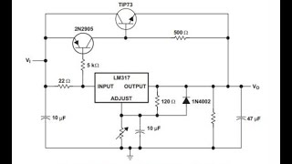
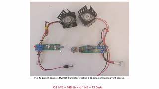
- Use a LM317 to control up to 5-10 amps through a PNP transistor.
Updated videos:
Measure Current from Constant Current Source with Arduino
• Measure Current from C...
Arduino Controlled Constant Current Source
• Arduino Controlled Con...
The actual schematic is on the webpage.
www.bristolwatch.com/ccs/LM317... - Věda a technologie


Please keep on doing what you are doing. Our students can learn a lot from you including myself. Very refreshing. Thanks for the information. People like you make a difference. Some people do lot of talking and criticizing but you put everything into practice. God bless you, though you are already blessed with knowledge.
This fella is very good at explaining what things are doing in circuit, he always has little gems of info that you would and will miss when learning electronics.🌟🆒📼
An absolutely incredible/valuable piece of information here. Thank you very much, sir, and...please don't stop bringing these,, treasures,, out to the world. Subscribed...:)
You are a patient man, Mr. Loflin.
Well explained, thank you for sharing !
Neat.
Useful.
Thanks for uploading.
I used tip35c.....work great in this cercuit.
Thanks for valuable information you gave us in this vedeo.
Thanks for your video. I'm trying to design a current limiting circuit for AC current, and one method I was told about was to use a linear regulator to regulate the AC current peak. At first, it worked fine with small current, but since I need to scale up to 2 amps, I was worried about the heat and power loss. Your video showed me a new way to go about it in a better way. Thanks.
This is not for AC. To limit AC power you really need phase control of the sine wave.
@@LewisLoflin Thanks for your reply. Why wouldn't this work to control AC current? My initial design using an LM317 as an adjustable current source clipped my AC current to not go past the set current limit of the regulator (set it for 10 mA, AC current won't go past 10 mA peak to peak, though it will draw less than that). The LM317 is placed after a rectified voltage (not smoothed out with a capacitor), so the current that passes through the regulator will return back to the rectifier in series with my test load. Sorry, it's kind of hard to explain it here, but I hope I get the idea across.
@@ZeusandHades It is a DC device - one polarity. AC swings from negative to positive.
@@LewisLoflin Sorry, looks like my comment got deleted. I'm just trying to build an AC current source that won't let the current go above a certain limit. My load is in series with the return path to my AC source. With the LM317 placed after a rectifier, it'll limit the max current being passed through my load by clipping it at the set limit. I tested this in simulation and on a breadboard and it works for small currents. I'm in the process of scaling it up to a larger max current.
Circuit works, but I was given the task by the recipient to bump it up to higher current than my demo. Thus, I'm looking for other ways such that I don't have to worry about power across the regulator when I stumbled upon your video for research (amongst others). Honestly, they want it super simple, so no Arduinos here.
Excellent project
Excellent lesson, many thanks.
This is a test circuit to teach transistor theory. The schematic in the video is not the main schematic but is on the webpage at
www.bristolwatch.com/ccs/LM317b.htm
This looks to be a circuit demonstrating students how If varies with Ib. As a current surve it won't be stable. With current on load the transistor's junction temperature will go on varying, there by changing the gain, in turn changing the Ic.
Excellent info,thank you sir
That's why you must learn from old school teacher.
Thanks
OK. I am confused but ok. What happend if i connected lm317 on my transformator 2*12 V/1.04 A. Can i up more then 1 A becouse lm317 is 1.5 A. Or on 317 connect mj2950 and then do i can up a current or current depends of windings in transformator and this is a limit?
Great video!
what are those amazing metallic cable clips at the terminal connector? necer seen them and they look fantastic to connect multiple wires while testing!
Thanks for doing a video on my question to you about driving higher loads.
Do all LM317 have this ability to run in Constant Current mode? and do the low dropout versions also?
Thanks Lewis.
Yes.
I think 2n3055 will work better....but use more than one transistor with power resistors on output for each one to balance the load equally on transistors for more power.
That way you have good powerfull current controll cercuit.
Thanks again.
How watts have your load of 10Ohm? Load P=?
I need to drive 3.2V 10W Led from 5V source.The drop Voltage of lm317 should be too much.Wich alternative?
very nice lecture! 👍👍👍👍👍👍👍👍👍👍👍👍👍👍👍👍👍👍👍👍
What happens to the current through your load if, all other things being equal, the load resistance changes 20%?
Thanks for video
excuseme if my question is a little ridiculous I am a beginner
Is it possible to use MJ11033 (DARLINGTON POWER
TRANSISTORS) with have very diferent hfe instead of MJ2955 (POWER TRANSISTORS) for getting higher power dissipation, lower thermal resistance and higher current
No. The gain is so high it would be impossible to control. In addition many of these Darlingtons have internal diodes and resistors.
the circuit is crap. yes u can use the darlington and the current will be all over the place.
Thank you so much.
Thank you so.much!.. I were in Thailand followed you.
If I need more Amp. Can I Do parallel the only MJ2955?
OR another way better?
Please....
Thank you.again and again!
suppose we have connected this circuit with 12 volts dc supply at its input and after this we set lm317 to 5 dc volts now at this point the transistor is in off condition and after this we connected a 5v dc load at circuit's output the load is high power and take more then 1 amps current due to this the transistor becomes on and as we know that the transistor works as close switch after on let suppose transistor don't drop voltage which mean 12 volts will be appear across the output capacitor as well as 5v load these 12 voltage can damage 5 volts load can you explain how we can safe our load at this point?
This is about current not voltage. Voltage is set by the load resistance times current.
Awesome!
If the transistor fail, then it will send the input voltage directly to the output. How to deal with it? maybe a simple protection circuit
Hello, nice video and explanation. I want to adjust the output of a ATX PSU, i don't have a power transistor, but i do have an LM317 and some mosfets (IRFZ). I need to be able to drive around 10Amps, which one to use ? thanks !
Mosfets are voltage operated bipolar transistors are current operated. No way to make it work.
@@LewisLoflin I have tried two irfz in parallel along with a 20k potentiometer. It regulates the voltage but are not efficient : i have a difference of 2.5v between source and the maximum i can get out of the potentiometer, and this drop gets worse under 8A load. LM317 alone cannot deliver more than 1.5 Amp ? thanks
can i use an ultracapacitor(2.7V, 120F) for charging it as a load in this circuit?????
Not sure what you are trying to do. The voltage for this purpose is too low.
sir, i want to charge an ultracapacitor 2.7V, 120F using a constant current source of 1.2A for 2min , so i need a constant current source. how to design a 2A constant current source????
See this webpage: www.bristolwatch.com/ccs/LM317.htm
Good Nice
Is there a more efficient way to deliver constant current to a load. The transistor is dissipating quite a bit of energy.
Yes I said that I believe. Step down the input voltage closer to what is required.
AFAIK buck converter regulating current is the closest to most efficient.
Sorry, I don't get one thing, How the voltage can remain constant.Transistor is connected here is like a jumper between input and output. Lets say input voltage is 20 volts and you set the output voltage at 5 volts and then start drawing enough current to turn the base emitter junction. Now the transistor is a jumper between input and output. How can voltage can stay at 5 volts. Please explain. Thanks
The firs ting is this voltage or current devider? For current you got a more things.
How watts have your load of 10Ohm?
Will this cercuit work with mosfets?
Some updated material related to this:
Measure Current from Constant Current Source with Arduino
czcams.com/video/AtBdjvbhNhQ/video.html
Arduino Controlled Constant Current Source
czcams.com/video/DL9Fb3o5px8/video.html
If we don't use a base resistor for the transistor in this type of circuit, will it overheat the transistor and the regulator ic when higher current upto 5 amps is drawn ?
You can add a base resistor noting that sets the upper limit of the base current. The current limit will be based on the value of R times Hfe.
Nicely explaination. Power lost generatng heat.
Exactly. That is why i say reduce input voltage then current regulate.
Heat makes resistors more resisting and therefore raises the resistance, other then that great vid
True. It also changes the gain on the transistor. This circuit is a demo.
you should change the battery in your multimeter
Have you successfully tested this circuit under high current like 15A continuously ?? does it survive short circuit ?
Yes I did and it blew the transistor. It ran fine at 10 AMPs, as for short circuit, It depends on the level of the short circuit.
It really depends on the heat removal rate from that power transistor. The heat sink he's using in this video is rather small, and not adequate for much more than a few watts dissipation. But with the proper heat sink design, a power transistor can handle 15 amps easily. I do recommend, though, that you never use this circuit for current regulation, and use a properly designed circuit instead.
Updated content:
Arduino Measures Current from Constant Current Source
czcams.com/video/AtBdjvbhNhQ/video.html
www.bristolwatch.com/ele4/ccs_lm358.htm
Constant Current Source Theory Testing
czcams.com/video/9ap49GaQPzY/video.html
www.bristolwatch.com/ele4/css.htm
I'm curious what are you powering with this circuit? Are you actually using this circuit for something or this just an academic exercise?
Battery charger, motor current limit, etc.
Any way to control the LM338 Constant Current Regulator Circuit digitally using arduino?
No there isn't.
And the digital alternative with LM338 like linear current adjustment no PWM is?
To control current digitally, replace 2k resistor at LM317 with digital pot and control it through I2C.
@@odissey2 Really, the output will be linear non PWM?
@@juliusvalentinas Yes. It will be operating same way as in the video, but controlled digitally. I believe there are plenty examples of controlling digital potentiometer by Arduino
Dear sir how i increase amps same power supply i have 25 volt power supply its operate motor controlling board but control board damage now i was make a simple circuit for motor drive but motor not proply work because low amps
Fuck
How much more efficient is this compared to just running the regulator?
If under 2 amps run the regulator alone.
This is an extremely bad circuit, and I suggest that anybody who is looking for a current regulator circuit look elsewhere. There is no feedback in this circuit, which means it relies entirely on the gain of the power transistor. This is all but useless in high current transistors as the gain is so low (typically
Read below - this is a test circuit to teach transistor theory.
Can you show me a high current regulator diagram. I love you’re comment. People will watch this thinking this is the circuit. It’s not to use. I see that. I would fry that circuit immediately. It’s useless.
@@donaldcampbell7894 Take a look at the LM317 datasheet. If memory serves, it provides an example of using it for high current voltage regulation using a TIP73 to supply the current as an example. That circuit would get you 15 amps.
Unless you need a shit ton of current, you should probably just use one of the higher current alternatives to the LM317 instead, the LM317 can only supply 1.5amps max.
This isn't a bad circuit. It really depends on the application. It's an interesting idea with 2 active components and some resistors, and it may work well depending on what its connected to, and the rest of the entire circuit.
I parllarly join LM317 *4 does this can handle 6 amp 24 volt input and can adjustable. If yes then what would be value of resistance used.
What is your desired output voltage?
@@LewisLoflin hi, my desired output voltage is 24 v 6 amp. I have a transformer rated 24 v ac 6 amp. When convert to dc it reaches approx 33 v
Hi waiting for your reply. i made power supply but my 10k resistance get sparked and burned when I adjust power supply. Any solution for it
@@satishsanhotra4391 Wait a minute. This is a current source not an adjustable voltage regulator. The output voltage is I X load resistance. What 10K resistance? The 32 volts is normal when 24-volts is rectified and filtered. If you are trying to operate a 5-volt device at several amps from a 33-volt source it will never work. The pass transistor will get red hot. The voltage regulation is separate. What voltage do you want on the output?
@@LewisLoflin first of all thanks for reply. I want to use output 24 v 6 amp DC. I'm having 24 volt AC 6 amp transformer. After rectifier it gives 33 volt DC. So i need to create a variable power supply. I used LM 317 t with D1047 and BD139, resistor used 220 ohms on LM 317 adjust and output pin and resistor of 10k to regulate voltage with LM 317. Problem is that my 10 k potentiometer get burn and sparked when I regulate the voltage through potentiometer.
Dear Sir, can i use LM350? & what is the value of the resistor used?
Resistor is the same yes you can use it.
@@LewisLoflin
Thank you Sir...
Greeting from Indonesia.
@@bravopapas4386 The people of Indonesia are wonderful people. Best regards.
Can i use 2n3055 instead of mj2955
No. That is an NPN.
Where is the feedback? The output current depends on the current gain of the 2955, which of course will vary with temperature. Not a great design... unless I'm missing something.
It is a simple design that works within reason. Thanks.
Is the lm317 gonna hot? Or only the power transistor will only got hot
The current through LM317 is only about 10mA. And voltage is about 15V. So power dissipated is about 150mW. Not enough to heat it significantly. I would say, slightly warm.
@@odissey2 thx, i already try it and it doesn't need a heatsink it just warm litle bit
@@ardhi1269 years ago, to simplify design, I built a power supply with about a dozen of LM regulators, producing various voltages for the system (+24V, +/-15V, 10V, 5V. Each one driving about 100 mA. That eventually required a heatsink and a fan, as the total power went over 10W.
How to select heat sink
Hi, I want to control high current (up to 40 Amps).
is it possible?
is there any PNP transistor to do this?
This is demo circuit and I wouldn't use it for what you want.
I am getting quite high Quiescent Current. Any solutions for that
There will always be some current through the base-emitter junction with the LM317. Put a transistor switch between the LM317 and ground.
@@LewisLoflin Thanks for your reply. You mean between output of lm317 and ground? One more problem which i am encountering is with the low ohm resistor. I am using 20 ohm potentiometer with 10 ohm resistor in series. Output current is 5 A. 10 ohm resistor fries when circuit is on. Do you have any thoughts on this??
@@amitpandey3975 Are you talking about the load resistor?
@@LewisLoflin No. One used to avoid virtual short.
you claimed that when the load resistor of 12 ohms got hot , the value then reduced to 10 ohms. i don't think that will happen. the ohmic value will surely increase not decease when the resistor gets hot.
I don't remember saying resistor. The resistors I used were wire wound and stable.
How pnp transistor gets biased.....because base of transistor connected to +
Current flows through the base-emitter circuit through the LM317.
An updated version of this video for 2024: czcams.com/video/y0PFBVVHMTA/video.html
wrong component using transistor on its own generator more heat the good using pnp mosfets D403 will give a more efficient circuit and a bjt with a current rating gain of 1.5 with will increase
This is a current-operated device. MOSFETs are voltage operated.
Feel for ya... a simple educational, theory video and the brainiacs freak-out...probably can't tie their own shoe's...
.
هلو
Are u musering curent in parallèle ! ??? Wtf !
What are you talking about? Current is measured in series.
Malaysia transistor....😀😀😀😀😀😀😀
useless...
10 amps maximum, sport.
That is the transistor MJ2955 rating. The reality is 5-7-amps for a safety margin. I use this circuit all the time for troubleshooting other circuits.
@@LewisLoflin I've used this circuit to do 10 amps.
@@Theineluctable_SOME_CANT Great! My problem was I got my MJ2955s off eBay, and they were off-spec. That is a risk one takes with eBay. Also, just so you know, as the transistor heats up, the Hfe changes somewhat; thus, the output may exceed the rated value. I mount the transistor on a large heatsink with a fan-thermister circuit. It is very stable at this point.
@@LewisLoflin it should regulate though because it is in a feedback loop.
Also, I never buy junk off ebay any more.
@@Theineluctable_SOME_CANT The LM317 itself has feedback. You learned your lesson about eBay.