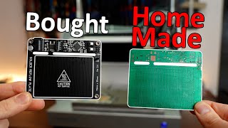
DIY PCBs At Home (Single Sided Presensitized)

Vložit
- čas přidán 18. 05. 2020
- Learn to fabricate Single Sided PCBs at home! Prototype PCB fabrication is one of the essential skills you must learn in electronics. Instead of using breadboards and perfboards, custom PCBs would make any project smaller and more compact!
PRESENSITIZED PCBs:
Also known as photopositive PCBs or photoresist PCBs, are regular PCB copper clads, layered with a light sensitive paint or film. Once exposed to light, the paint would dissolve in the developing solution, while the unexposed areas would remain undissolved in the solution. This forms a Mask on the clad. When the developed PCB is exposed to an etchant, the masked areas would remain in tact while the unmasked areas would dissolve on your etchant, thus forming a copy of your printed PCB artwork.
WHAT PAPER AND PRINTER TYPE TO USE:
- You can use an injket printer for this type of PCB fabrication, no need for toner printers.
- I use regular Short Bond Paper (Letter 8.5x11"). You can use parchment paper or inkjet friendly films for better fabrication quality.
BETTER THAN TONER TRANSFER METHOD:
Toner transfer method has been the number 1 go to in homebrew PCB fabcrication, next to the sharpie method. Toner transfer has its own limitations. One, is that you would need a toner printer, common inkjet printers simply wouldn't work. Second, as your line traces gets thinner, it would be more difficult to transfer the toner prints to the copper clad. Presensitized PCBs on the other hand creates the sharpest lines of all the homebrew fabrication methods. This is perfect for smaller circuits that involves SMT (Surface Mount) components. I use this method for building PCBs with line traces reaching down to 10mils (0.254mm). You can go as thin as 5mils (0.1275mm), but you would have to use inkjet friendly acetate.
_______________________________
Instructable Tutorial:
(www.instructables.com/id/Sing...)
DIY Etching PCB Shaker
(Link: • DIY PCB Shaker For Etc... )
DIY Digital PCB Exposure Box!
(Link: • DIY Digital PCB Exposu... )
_______________________________
Tools & Materials:
1.) Photopositive PCB Pack
- AliExpress: bit.ly/2WLOi0F
- Amazon: amzn.to/3bRbz5n
- E-Gizmo: bit.ly/2ylwhNi
2.) Ferric Chloride (Copper Etchant)
- Amazon: amzn.to/3cZu8pL
- Lazada: bit.ly/2ZkjPIF
3.) Pure Acetone (Nail Polish Remover)
- Amazon: amzn.to/2zdVOIE
- Shopee: bit.ly/3cOF4q3
4.) Baby Oil
- Amazon: amzn.to/2ZrII54
- Lazada: bit.ly/36gZLsb
5.) Mini Drill
- AliExpress: bit.ly/2XaTJVX
- Amazon: amzn.to/2ZiHBoi
- Lazada: bit.ly/2LVDPtr
6.) Drill Bits (0.8mm - 1.0mm)
- AliExpress: bit.ly/2WJNI3n
- Lazada: bit.ly/3bReoU1
7.) LED/ CFL/ UV Lamp
- Amazon: amzn.to/3bOFoUq
- Lazada: bit.ly/2WL9kfE
8.) Cutter Knife
9.) Hack Saw
10.) Wooden Plank
#Circuits #Electronics #DIY , Kinsten PCB - Jak na to + styl


Please wear latex gloves and wear protective goggles when dealing with these chemicals. For this video, I ran out of gloves at the moment due to the massive shortage of medical supplies due to the COVID19 pandemic. Lye (developing solution) can be corrosive to human tissue, for this project, the concentration of lye is quite low. I washed my hands thoroughly after getting exposed to it. Ferric Chloride on the other hand barely has an effect to human skin, but it does leave a stain on everything when not immediately rinsed with water. Stay safe fam!
The number of views would be more if the video were translated into Arabic
The number of views would be more if the video were translated into Arabic
czcams.com/video/F9ft8d5T0Is/video.html
Thanks for your
Just a very important FYI: Do NOT pour down the sodium hydroxide solution down the drain. It now contains copper(II)-hydroxide (or rather a hydroxy-complex, that's why it's blue!) and that is not very good for the environment. You actually have to bring that to a hazardous waste disposal facility. Yes, really. Your local wastewater treatment plant will thank you for not making them deal with heavy metals.
Also, please store acetone in a very well ventilated area (preferrably outside!). Acetone has a very low flammability and high vapour pressure - if you're really unlucky you'll blow yourself up. Not a joke.
Brings back memories. Back in 1985, we technicians were making our own boards for all sorts of stuff. One of my pet projects was making a PAY TV decoder. I designed it so that it decoded the video line by line rather than the standard frame by frame method. Thus there was no need for a PLL ( phase-locked loop) circuit. It was powered by 12 vdc, and it only pulled about 12 mA, and the board was only 1.5 inch by 4.5 inch. So you just installed it inside your TV converter by tapping the converter's 12 vdc power line, and then cut the video connection that connected the RF demodulator to the RF modulator, and then feed these wires to the tiny decoder board. And that was it. You now had a PAY TV decoder. It decoded all the PAY channels, and did so instantly, since there was no PLL delay. Meanwhile, the engineers used the standard method that required tons of IC's and other components, and it therefore pulled plenty of current, so it needed its own power supply, and of course it needed its own box as well. That costs money. Mine, only had three IC's, MC4013, MC14538, and an LM393, plus a few transistors, diodes, etc. So making just one, cost about $5.00 total. Those days were fun indeed.
How do you learn about all of that stuff? Can you still use a similar workaround today for paid channels? That sounds so neat!
@@426F6F No
relevance?
That's so nice! I would have liked to live in that time, a simpler time where technology was less integrated into society and solutions were more practical and simple. There is no way in which something like this works today, technological innovation has been displaced and relegated to mega-corporations with funds of millions of dollars to allocate to research.
@@426F6F modern tv is digital and uses encryption similar to what the internet uses
That was, hands down, one of the nicest and easiest to follow CZcams tutorials I've seen in ages! Thank you for that! :) So many content creators mumble or talk waaaaaay to fast without taking the time to speak CLEARLY.
Thanks man! Means a lot! I wanted to make a tutorial on PCBs for years but I found out a lot of people already posted it. I revisited some of the classic tutorials only to realize they weren't first-timer friendly, so I made this vid anyway hahaha 😊
Honestly, before I saw your tutorial I always imagined making your own PCBs was a way more complicated and chemically hazardous process. Glad to see it's actually way easier than I thought!
"Only peel the PCB in a dim room."
Proceeds to peel the PCB in a room brighter than the beaches of Normandy.
yeah
BTW ev8, have you become a flat earther yet?
I mean, he's filming.
Doesn't matter as long as all light is artificial from LEDs, they have zero UV output and the film is sensitive only to UV, so even dimmer sun will start reaction while several thousand lumens of LEDs won't
@@flat-earther🌍🌎🌏🌐
Overall a good tutorial. Just 3 remarks.
1) There is a easier/better way to cut PCB material that also works with glass-fiber and double sided material. Score BOTH sides 2 to 4 times with the sharp side of your blade, then snap.
2) Temperature is important for development and etching. Do both "au bain marie" in a tub of hot water, to get around 30C - 40C. You may find you get better results and the chemicals can literally last years.
Years? yes. My etching machine holds about 2 liters Ferric Chloride. The same Ferric Chloride has been in there for over 10 years and was used to etch almost 2 square meters worth of double sided PCB material. I add Hydrochloric acid to compensate for evaporation and keep the solution active, even though there is now a lot of copper in there.
3) Please be safe, pure Ferric Chloride only stains HOWEVER the Copper Ferric Chloride mixture you get after etching is rather poisonous.
One tip is to leave as much copper on the board as possible, and only etch the spaces between the traces. Usually there is an option in the PCB software like "create ground plane". First, this reduces the amount of etching required significantly, extending the life of your solution. Second, you will have more uniform etching, since there are no areas that get exposed to bare etchant for a long time. Third, you'll have a ground plane to help reduce interference and make your trace impedance more consistent (important for high frequency or timing sensitive applications).
So etching is just an engravement on the copper board?
You explained everything in a simple, straightforward and slow pace that made it EXTREMELY understandable. I hope you become a teacher because you have a great skill at presenting information. I also admire your ingenuity at building the machines you needed to finish the project. Well done!
Definitely brings back memories from 1980-ies. When I made my DIY PCBs only in such way because there were no better ways.
TechBuilder , you have just gotten me out of the months-long toner-transfer vicious circle - in 10 minutes and 10 seconds! Thank you greatly for that!! Every day is a new lesson!
This is my preferred method of building PCBs too. I use transparent sticker paper instead of the paper and oil. It’s too messy :) The transparent sheets are think and stick to the PCB thereby reducing the gap between the film and the PCB. The lines are more defined with this and I was able to get clearances as low as 0.3mm and track widths of 0.25mm with this.
Any sticky paper?, and im gussing you print your schmatic to the paper and then just slap it on and the do the rest of the steps?
@@jacobnoble2167 not an opaque paper sheet. I print them on a transparent sheet that can be printed on an inkjet printer, but with one sticky side. They are clear transparent plastic sheets that can be printed on.
@@hrishikeshb Could you link what your talking about and im guessing you print on the non sticky side? THen Uv expose... etc
How I wish this quality tutorial existed 7 years ago. Tough times.
I feel ya
Now thats an interesting approach, by some miracle a local store is selling positive presensitized boards, will have to try this. two thumbs up!
I wish I had a store like that
You have a local store selling electronic components.. I envy you.
@@booruvcheek1331 You would be surprised. But they are slowly dying
I usually don't comment on videos, but this is something else. Very clear& easy to follow. Definitely worth subscribing
Peat
1年前
I usually don't comment on videos, but this is something else. Very clear& easy to follow. Definitely worth subscribing
Wow the real tech builder and your workshop looks amazing.
Thanks for sharing.
I love how organized your closet is.
Man... you are an asset to the whole world! Hope you shine more and share your knowledge with te world! Thank you!
Thanks man!!!
I kinda knew the process before but this made it so much clearer. It was super easy to follow and had all the information needed but none of the fluff. Thanks dude!
Great video. I hardly know what a resister and a capacitor is but I’m gonna go out, buy a bunch of things, and make a circuit board. That was such a good tutorial,fascinating.
This is the best PCB tutorial I've seen. Thank you!
Amazing content. Clear and educational. Thank you.
Thanks! :D
That was great to watch. Forgot how many steps are needed to produce a simple pcb. This video was an eye opener. Great work!
Todays offer from JLCPCB 100x100 mm2 two sided with solder mask and silkscreen 5 pcs = $2 plus shipping .... DIY PCB does not really make sense anymore, too bad, I liked to do it.
Watching this I noticed countless things that would make the process better. But then I realized that you are showing the most basic and simple way. One thing that I have learned about cutting the PCB is that a good heavy duty pair of scissors does the job surprisingly well. You might be worried about ruining the scissors. If you are you can buy a cheap pair just for the job.Thicker PCB would be a challenge for scissors but the thin ones like you made are not a problem.
For those without a laser printer, this video is priceless! Thanks!!!
Glad it helps!
just started electrical engineering and this got me super excited for it
Great video as always. And, presentation is slow, calming and comes across as do-able by the watcher without previous experience. Perfect for tutorials, and excellent, interesting projects.
Your explanation is so clear and simple yet you covered the topic very well!
Thank you!
Really a clean and good demonstration on how to make PCBs. You have simplified it.
Can't wait for your video on the electric car circuit. Exactly the kind of thing I've been wanting a clear and concise explanation of.
Thanks man! Almost done filming it! It may take a few more months, due to my video edit lineup.
Thank you! This was very helpful. Did everything as suggested. Printed my designed circuit on A4 plain paper with laser printer. Did some testings to find the right recipe for my conditions and I found that paint on paper are tend to blur after contacting with cooking oil, so I used spray varnish to protect my paper circuit before applying cooking oil. This worked perfectly.
This method is meant to be used with an inkjet printer.
Excellent! Clear, detailed and well-paced explanation. Thank you very much.
Awesome video. I built a UV exposure unit into an old scanner body with 3W UV LED's. It took my exposure time from 2-3 minutes to 12 seconds with perfect results.
incredible, I loved the video. I can't wait to try this myself!
Have fun! Drop a comment here if you experience some difficulties in the process, I'd be happy to help.
2 Cool points for the guy who remembers the part number of the Radio Shack kit for these boards. Man I miss that store:(
Got nostalgic when I saw your Sadiku Book. Brings back college memories. 😅🙌
Ferric chloride etching can be significantly sped up (3-4 minutes) by heating the solution. I usually put it in a cooking glass container on the stove and heat it on the lowest setting, while agitating the solution and board with a stick. Toner transfer can yield same results and much cheaper. I made quite a few SMD boards with close traces (QFP32) and even one double sided board (even though I admit the alignment was tricky and got it on the second try).
You should swap the paper with a Overhead Transparent sheet, then the PCB traces will not have all the inperfections that your resulting PCB has. (pixelation and small holes.) Print the pattern Mirrord, so the printed side is turned with the printed side against the Photo-resist dirrectly to reduce bluring of the edges of the traces.
Perfect timing. I was searching for ways to transfer ink to pcb
czcams.com/video/F9ft8d5T0Is/video.html
Your voice tend to make me think you're very young. Hope you inspire many guys around the glove. I like your techniques and very well documented video. The chemical in this country where I live cost me a lot, unfortunately. Nice job. Thank you keep it!
Thank you. You have done a fine job of explaining this process.
Thank you. I had given up on it because I thought I had to do toner transfer. Doing it with inkjet is amazing
Same! Agree!
this is the best video i've seen related to this yet. i hope it spreads
Thanks!!
This brought back memories for me, I used to make a lot of prototypes this way.
Same! I brought back some memorable moments when we used to compete in robotics and fabricated circuits with this method. These days I only use it when I need a PCB done within the day since Chinese PCB fabrication services are becoming a lot cheaper by the day.
@@TechBuilder I used the black tape and transfers for small runs as they give clearly defined boards, you can also get Etch resistant transfers for one off prototypes
@Timothy, same as me. Used an old tanning lamp for the exposure light. So much easier to pay $2 to get a professional board done!!
@@favesongslistah the black tape and transfers, that dates some of us , fond and annoying memories.
Personally I recommend spraying the PCB with a solder-through lacquer, especially if it's not being used immediately. In the longer run, it helps prevent corrosion. Alternatively spray the track side (on single sided PCBs) after installing components and making sure any flux is cleaned off.
I also score both sides of the board before snapping (and I use the sharp side of the blade). I've also been able to snap-break glass fibre boards that way. Also, I'd recommend using tungsten carbide bits for drilling PCBs as the standard hss types tend to blunt very quickly, especially with glass fibre.That can matter for accuracy when drills become dull.
Thank you for the tips. I'll be making my own pcb for a project in the next few weeks.
@@KE8UYV Good luck, as it can be very frustrating.
One of the best guide I ever saw
I managed to make .008 inch (0.2032mm) traces pretty reliably with similar technique, except I sprayed Positive 20 photoresist on polished FR4 PCB, using inkjet printer with the color cartridge filled with all black ink, set to high resolution photo and and photo paper settings, but I actually used normal paper instead of photo paper. :D
That was achieved with my old HP Deskjet F2480 printer, and regular 80g/m2 paper, and cooking oil to make it transparent, as you mentioned. Now I bought a new pigment based (HP Deskjet Ink Advantage 3775) inkjet printer, and high quality 90g/m2 Xerox Colotech+ paper, which has smooth surface, and it actually gets more transparent when the oil is applied. I bet it's gonna be even more reliable once I perfect the method, although the old printer really soaked the paper with ink making it really black, this new one, does not even at high resolution photo settings although it looks even blacker then with the old printer, it's kinda transparent black(which is not good)... I'm thinking if I can't make it work with the new pigment ink, I'm gonna experiment with mixing pigment based, and dye based ink to get the blackness I need to achieve even though it may ruin the cartridge.
That was hands and foot down .
Verry helpful video thanks.
What a relaxing way to learn something
This is so HOME-MADE I even want to try it :D
TY! sir
That was really informative and comfy to watch. Sad that you stopped uploading videos to this channel
Great video! You really made the process easy to understand. I need to try this sometime.
Very nice and straight forward instruction. I used this method around 20 years ago already ;-).
One suggestion. Use laser printer instead. The lines will be much more accurate and edges sharper. You can also experiment with printings on a foil.
yes, a laser printer, we could go down to reliable 6 thou tracks with a laser printer. also 0805 SMDs. SOICs and so on.
Very easy to follow. Simple instructions, practical approach. Quality audio and visual. Instructions and example and explanation. Overall excellent stuff thank you! This is how you know when someone knows what they're doing.
Wow, now that's a tutorial. Thank you!!!
Thanks!!
double sided works well too, just tape the topside acrylic transparency to the underside by one edge, fit a double sided PCB inside and expose.
remember to have the printed side closest to the copper, then theres less or no diffraction errors from the light box.
use the pads to align both layers then tape. as long as tph pads are big enough to allow for slight misalignment, should be golden.
we used this method for small scale commercial prototyping late 90s, the benefit is you can make a prototype PCB in hours. from CAD to construction.
using a proper PCB production company takes a day or two, depending if theres a local one.
Problem with DIY double sided are through hole plating. Try to get a 44 in PLCC socket to make contact with both sides. It's impossible. If you have simple discrete components you probably can get an iron on both sides, but not with many components.
You are so organized!!! Very Neat job man. Keep it up.
It helps me a lot with my workflow, thanks! 😊
Thanks for your clear exploitation. Gone give it a try.
Well thanks for the video and the hint that we can also use normal white light, I totally had forgot this 😅
great job on the tutorial, will try it myself. Thanks a lot
Great tutorial, much appreciated!
Super cool video! I didn't know that type of DIY pcb existed.
czcams.com/video/F9ft8d5T0Is/video.html
I took electronics in HS in the 80s and we had the machines to make boards like this. I still have four of those projects.
Thank You ! for building the confidence.
Keep it up! :)
Thanks making this video simple.. most easiest video for my brain to process the step by step information
My dad whose main hoby is electronics (he built his own radio at about 20 yo) still uses this method and so do I for some of my projects
excellent tutorial about making the pcb. Superb.
Very nice, I did this in the 80's with regular pcb boards with decalcs and permanent markers. Now with this light transfer method make things lots easier.
I recall doing photo resist in the 80s, but you had to draw the circuit by hand!
Ok. I did try this. Took a few attempts but got it working. Here's my advice:
I use a 4x8W UV lamps exposure unit at a distance of about 10 cm. It takes 10 minutes (anywhere between 8 and 12) to get proper exposure
I oiled the paper separately, dried it off and then put it on the board. Way less messy to clean up later, it only takes some water and a drop of dish soap
I used 6g of sodium hydroxide in half a liter (500mL) of water and it worked very well by leaving it in there a bit, agitating it with a brush. I think it got saturated though, as I needed to redo the solution midway. Maybe a liter would be the better choice
I used a 1:1 ratio of ferric chloride and hot water to etch. This saves some time and cuts costs of etching
I got very good results using 0.762mm traces, perfect definition this way. I think I could go down to 0.254mm if I wanted to, the results were that good
Overall this was a great video to learn basics, I just needed to perfect my method
Amazing tutorial thank you so much really enjoyed
Wow very beautiful result at the end I'll save this
Dude, just wow!
Very informative video Angelo. I came across photosensitive PCBs in your FM transmitter video! I have never tried it, but I might just try them for fun. Also, we need a FM transmitter v2!
Thanks! It is! It's a bit expensive on western countries, but for Asian countries, big Presensitized PCB boards are dirt cheap. I would still recommend the classic toner transfer method fabrication for PCB designs with thick traces as it would be a lot cheaper. For tinier boards, nothing beats Presensitized PCB fabrication, except for professional PCB manufacturing (like JLCPCB's services).
Nice & straightforward. I would add a cautionary note about using acetone inside, you MUST have good ventilation. It evaporates so quickly you can build up a dangerous level of highly flammable fumes in short order.
Thanks... that was new start for me ,as beginner in electronics ,
Welcome! Hope it helps 😊
ho god, you are an hero man .. I never know this type of pcb
This was extreamly impressiv
Thank you!
Interesting to see you just use a paper printout. I've always printed to high temperature overhead transparencies. Your way of wetting it and sticking it to the board saves any unwanted movement.
Transparencies give the best results! I do find the inkjet and oil more economical. Yes! The oil really helps with the grip! :)
Ok so nobody gonna mention how he used his bare foot to hold that PCB down????????
Awesome tutorial! However I would suggest that people not think of lye as “a mild soap.” It becomes soap when it dissolves lipids and proteins. If it feels soapy guess where those lipids came from? Also keep the solution in HDPE plastic (number 2) or glass preferably, and never anything aluminum. You might not even notice that you’ve burned yourself with it for several hours.
I use vinegar and salt to remove the copper. It works best over low heat while agitating.
I have done this with the toner transfer method. I assume it would work with this also.
Great video.
It looks far superior to the toner method.
Holy crap!! This looks WAY cheaper than shipping JLC PCBs from China!! Thank you so much for this!!
There are definitely pros and cons. I do DIY pcbs when I'm iterating through changes and making sure my circuit is right. In fact I just did one the other night and forgot to add power pins to one module in the schematic. I usually do breadboarding first, then make the schematic from the breadboard, depending on what I am doing.
Doing the board DIY allowed me to find that problem immediately, as well as changing some button placements which went through the back of the case for user input/selection. Once I'm satisfied, however, I'll get professional boards done. It's still very cheap, and having a solder mask and tinned pads makes it way easier to solder, especially if you have small SMT Ics with pins which are closely spaced.
Very informative. Thank you so much.
Nung nakita ko yung Summit. HAHAHA Pilipino to. Pati pala sa pagsasalita. By the way ganda ng content!! ❤️❤️❤️
Really Great tutorial! I am starting to learn how to design PCBs, hopefully one day I will get to make my own from scratch like this!
its easy, just start off with simple and larger track/pad PCBs, nothing too complicated or complex while learning the technique.
The video I was looking for. 💚
YT recommended this video and I watched the whole thing.
very interesting and useful video, thanks a lot .
Hello, I'm from Russia! Thank you for the video, 73!
Welcome! Greetings from the Philippines my good sir!
That is pretty cool. Thank you for sharing with us.
Nice video. One correction though: sodium hydroxide is not the main ingredient of soap, but is used to make soap from fatty acids. It’s actually the main component of drain cleaner, or “liquid sosa”
I can't be more impressive more than that , great job dud 💙🌸.
Thanks man!
@@TechBuilder
I totally support you 🌸.
that precision 😎
Very well described tutorial you are a master at explaining clearly and very precisely what to do !! awesome! Can we use vinegar as etchant?
We love your tutorial. Thanks 🙏
This is such a cool video! Thanks for sharing!
Looking forward to seeing your tutorial on the PCB Shaker please :-)
I just started filming it! It will be out soon! 😉
@@TechBuilder Amazing, thank you ! :-)
Been following you since you dropped that BB8 diy video, that really catch me on arduino but was too young to understand a lot of that stuff at the time.
Now I'm ready
Extremely helpful tutorial, than you!
Great video, I find that if you warm the Ferric Chloride in the microwave to about 50/60C before you use it it works a lot better
I'll try that. This man!
nice first descent tutorail on making pcbs