MCP42100 Digital Potentiometer with Arduino

Vložit
- čas přidán 26. 07. 2020
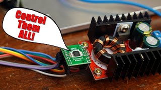
- Here's a look at the MCP42100 digital potentiometer, how it works, and how to control it with an Arduino.
There's a couple of practical tests including a DMM resistance measurement of the pot as Arduino changes the wiper position, and an op amp circuit where the digital pot is used to control both the gain and the reference voltage on the op amp. The oscilloscope shows the impact of the digital pot on the waveform.
MCP42100 Datasheet:
ww1.microchip.com/downloads/en...
Sketch:
github.com/GadgetReboot/MCP42...
Patreon: / gadgetreboot
#ElectronicsCreators - Věda a technologie


You just saved me hours of figuring this out! Thank you so much!
Excellent overview. Thank you for sharing this.
This is great! I do have an idea to use these as a digital audio board . Slide pots on an touch screen. Fully digital audio level mixer.
Helpful video. I liked it
Very Good information , useful to me
Thanks for sharing
Thank you !!
Good information.
Interesting.
I've played with the X9Cxxx ones before, but I wasn't aware of these SPI ones.
It's always handy to have multiple ways to get to eh same place.
I only learned about this family a couple of months ago. If anything, I am most impressed that they actually worked considering where they came from. My batch of X9C were the wrong resistance.
Great subject, and good timing on my part. I've been wanting to try these digital pots for some time now. The idea is to make some king of a graphical user interface for an audio application I am working on. I wonder how much (if any) digital noise will be mixed into the audio signal when a MCU and all those data lines constantly switching is included in an pure analog audio circuit...
that’s where some trial and error may be needed, especially if it’s done on a breadboard and not a printed circuit board with a good layout, things like ferrite beads in series with the power rail to various chips might help filter noise, or even using an isolated power supply so noise can’t get in that way and using Opto isolators or digital isolators for the control of the pot so there’s absolutely no electrical connection.
Thank you.
Great video. How would I control a 0-10v circuit using a digital pot and arduino?
Great video. How can I control the digital pot using a rotary encoder.
It's potty time, look quite useful. If you used one to say set a bias setting, I'm not sure how the circuit would behave if they become active after the components around them. So on power up does the OpAmp output hit any power rails as the +Ve input might be low or floating until the pot has settled ?
yeah there’s definitely considerations with power on settling time, I wonder if it would work to have a couple of higher value fixed resistors as a divider to keep the bias near target and then when the digital pot kicks in it may not have a linear response but it may allow the tweaking in parallel with the fixed resistors
I'm trying an AD8400 to replace the potentiometer in my trolling motor foot pedal. First step is to control it with an arduino... after that I'm integrating a GPS, compass, and encoder to do station keeping and automatic heading correction
What is the max threshold of power rating on this MCP digital potentiometer, example it has 10K resistance but what wattage it can withstand?
good video.plese can you help me to used MCP4162 ? i'm blocked on code arduino
With the X9Cs you can wire the two inputs directly to a rotary encoder’s quadrature output and get a relatively cheap multiturn potentiometer, plus you could use the button on the encoder to change which digipot you’re controlling or do something else with the encoder.
this sounds familiar, I think I was playing around with that a couple of years ago... czcams.com/video/HJWMFebfPrI/video.html
Gadget Reboot oh, you have too! I’ll need to have a closer look through your video backlog for more!
I take it this chip doesnt have a memory similar to X9C's?
No memory, the wiper goes to the middle upon reset/power up.