Digital Potentiometer Control / DS3502 / VFD 3 Phase Control

Vložit
- čas přidán 23. 07. 2024
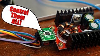
- This video will describe how to interface the DS3502 digital potentiometer to a microcontroller. A Scamp3 board running FlashForth will control a 3 phase induction motor using a VFD as an application example.
ScampPOT.txt code:
www.dropbox.com/s/pwzsunn8yxf...
Scamp3:
www.tindie.com/products/johnc...
udamonic.com/what-is-a-scamp....
FlashForth:
flashforth.com/ - Věda a technologie


Once again, very informative. I’m learning a lot from your videos. Keep it up.
Awesome. I really like these Scamp3 videos. Much easier than an Arduino. More please.
More to come!
Cool looking machine near the end. About 30 years ago I was mechanic in an industrial wood working company and a lot of this seemed like fairly new technology. I was a truck and forklift mechanic, but I remembering I wished I could get more involved in the electrical equipment. I got to help out the one electrician who was my boss and learned a lot from him. The job didn't pay well, but I learned A LOT there! One of my favorite things was the 60- 400 hz frequency changer we used to run a brushless motor router at 10,000 rpms with. It did this mechanically with a motor driving a generator bolted to it. I just got my ham radio licence, but didn't know a ton about electricity. I don't know if they had VFD's back in 1993 or even what they were. Thanks for recommending!
Never used a digital potentiometer before. I think I might give it a try. Thank your for the introduction.
You're welcome.
Nice work. First time to know about digital potentiometer!!. I remember that there is a way to let a MOSFET work as a varying resistor as well by varying its base voltage. Correct me if I am wrong
Yes ... you can also use a MOSFET driven into its "ohmic" region.
I've used the Digital Pots for some PIC projects a few years back. It is to be noted that the Wiper max current is not high and can easily be burnt out or damaged if not respecting the data sheet specs. Another good video ;-)
Yes ... 1 mA is the maximum wiper current. This caught a lot of people so I made a video just on that subject. I thought it was deleted but I see it is still up.
czcams.com/video/7sMU7vzpo3Y/video.html
@@0033mer I remember that video.... Man.. How time flies...
Another great video, thanks Ken.
Welcome John.
Excellent! Thank you.
You are welcome!
Indeed, awesome !
Thank you! Cheers!
Thanks!
You bet!
Another way to do it would be to use PWM from the controller and level shift to 10v by using a single transistor. Do you see any particular advantage of using the digipot in this case?
My thoughts too. Digipot is a kinda expensive alternative to a dac or filtered pwm and an opamp
The VFD supplies the 10 volts and a pot is meant to vary the control voltage from 0 to 10 volts as seen in the user manual. You can go the PWM route which works ( I have a video ) but you will find to get the full 0 to 10 volt swing, the power supply has to be greater than 10 volts which was not available on the VFD.
nice vid what if u use a arduino to control it and and a input resistor to control the out put
Im curious where the 127 number comes from. I use midi sound gear all the time and the values you get are from 0 to 127, so obviously theres a reason. For pro audio gear, is 127 different resistor positions enough for smooth audio sweep? Is it possible to go higher? Or is 127 just the max about of data that the midi standard can pass on a given channel?
The DS3502 digital pot is comprised of 127 resistors in series, so the wiper position is from 0 to 127. Midi volume (velocity) values are also 0 to 127 as per the midi protocol. Chip manufactures could use more resistors for finer control but 127 seems to be the industry standard.
@@0033mer This answers questions ive had for years. I never knew how digital pots worked. Makes a lot of sense and is actually pretty simple. Thanks much!
I don't know how to login to the scamp3
I know it's probably easy but I just haven't found and information on it.
Basically you plug the Scamp board into the USB port of your computer and run a serial terminal program like Tera-term or Putty. Set the baud rate to 115.2k N81 and you should get an ok prompt. Check the Scamp website for more info on getting started:
udamonic.com/getting-started.html
Interesting content but your diction is very monotonic
I think the videos are good. Your comment is a bit rude.