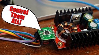
Digital Potentiometer and Rotary Encoder Direct Control X9C103

Vložit
- čas přidán 4. 08. 2018
- How to control the X9C103 digital potentiometer directly from a rotary encoder with optional switch debouncing.
If you are only controlling one digital pot at a time and don’t need to store the setting for power on recall, you can just keep chip select enabled at all times. Otherwise another modification would be required for more features but this is just a simple hack.
The rotary encoder used here has 20 positions per one revolution and the digital pot has 100 wiper positions so this is in effect, a 5 turn multiturn pot as well!
Blooper List
- I think at one point I said 500 ms when I meant 500 µs but I think that’s easy enough to catch and filter out within context.
Patreon: / gadgetreboot
Pinterest: www.pinterest.ca/GadgetReboot
Twitter: @GadgetReboot / gadgetreboot - Věda a technologie


Nice demonstration.
Much cleaner then my mess of jumper wires when I tried to demonstrate the digital pot chip.
I don’t think I saw that video. I will have to go search it out. You should see the mess of wires and other things on the work bench outside the video frame. I really need to do something about that it’s been building up for half a year.
I like to think that everyone's shop is a jumbled mess just outside the camera's view. I know mine is.
I didn’t do a separate video about the digital pots, it's part of my Dec 17 (2017) mailbag Monday.
Guys, it is reassuring to know that beyond the 1920 x 1080 pixels of relative cleanness I see in your videos, there is a mess that looks the same as the one I have on my own bench :D
Nice scope shots of the (de)bounce.
Have seen a similar circuit to drive a binary counter from a rotary encoder.
Maybe the target application of this digipot is to replace a (expensive) multiturn potentiometer with a (cheaper) rotary encoder.
Yeah I never thought of this as a multi turn pot. My encoder has 20 detents per revolution so this is a five turn pot with 100 positions on the digital pot.
Excellent! I did not have the imagination to figure that one wiper would clock, and the other determine the direction. So simple. Seem to remember from the datasheet that it allows you to elect if it keeps its setting on power-down? Yes, this is sweet.
Now, thinking that you can use your dual-D's and a 2-channel switch (maybe a CD4066B) that sets levels on several X9Cxx chips with the same (expensive) rotary encoder, and a few inexpensive buttons -- all without using an MCU. May be good for something like a PWM generator that uses multiple resistance values -- frequency, amplitude, duty cycle etc.
Yeah it took me a while to realize we don’t really need a circuit as long as we’re only controlling one device at a time and we don’t care about Chip select we just keep the thing enabled. I forgot to mention in the video that I was keeping chip select enabled and we would need another way to control that if we wanted multiple devices.
Could wire the encoder press button to a binary counter and use the output of the counter as chip select. Then its easy to add or remove devices, as you just wire (number of devices + 1) to reset of counter.
@@annybodykila Hmm, like a CD4017 decade counter, where Q0 is no device, and Q9 resets, to select 0 to 8 devices? Some debounce circuitry, indicator LEDS, and maybe even one of those cheap 3-digit voltage meters, that would be a useful device.
nicely explained, thanks
How good this can be for audio applications? Any signal quality losses?
AWESOME!!!! Thank you
Excellent
I'm trying to replace a 24v step-up converter's pot with a digital pot so that the user can select the voltage digitally via program instead of manually. I don't know if I make sense but is that possible?(converter is connected to the VCC of arduino and terminates to a 3-24v buzzer)
The two limiting factors would be the maximum voltage allowed across the terminals of a digital pot as well as the maximum wiper current allowed. If I remember properly, the maximum voltage across this digital pot is +/-5 V and the maximum current allowed through the wiper is about a little over 4 mA.
I was thinking about doing something similar but when I put a volt meter across the terminals of the existing trimmer pot on the regulator, the voltage was beyond this safe value so I couldn’t do it, but other circuits may work differently. So you could do a quick test measuring the voltage across the pot as you adjust the converter through its range and see what the maximum voltage is across the terminals on the pot.
Thank you.
Hi great video
I noticed on your schematic there was no indication of a chip select Do you only need chip select when interfacing with a microcontroller Or is it not needed in a manual situation like this
I just kept the chip enabled all the time since it’s only one chip. If multiple potentiometers were being controlled by the same data lines, that’s where each chip would have its own chip select so the one set of data lines from a microcontroller can send out the data and enable whichever chip they are targeting and that’s the one that will get controlled at the time from the one set of control signals.
How to control the X9C103 digital potentiometer directly from a rotary encoder with optional switch debouncing I want this conding pless reply me
I know you said no CPU's but you could use a Tiny 85 or something, that would give you software debounce & you could set the resistance increments to 1 decoder click?.
yeah a small cheap processor is always more practical and robust but it’s always a fun exercise to think about other ways, and then maybe those other ways can lead to other ideas for different projects too.
HELLO !!
There are 3 resistors on board of the rotary encoder. I am using the same module as you are using. So even though we have those resistors , should we use the 1k and 100ohm resistor ? What is the actual function of the on board resistor ?
The three resistors on the encoder are 10K pull ups for Clock, data, and the push button switch to give us our logic high signal or ground when the switch is closed. So when using the encoder we don’t need the external pull up 10 K resistors but it wouldn’t hurt anything it would just be in parallel with the encoder resistors and end up giving a 5K pull up resistance.
We do need the 100 ohm because that combined with the capacitor provides the debouncing and filtering on the mechanical switches to give us a filtered output instead of all kinds of bouncing high and low signals so it’s a different function than the pull up.
@@GadgetReboot thank u for the detailed explanation 😊
@@GadgetReboot I used the same schematic with the nodemcu. But the reading is not stable . The output is jumping around. I am trying to dim a light with the rotary encoder. But not with the digital potentiometer. Is this schematic only for digital pot ??? or can be used for other purposes ??
This schematic happens to work with the digital pot because of the way the two controls work on the digital pot. Increasing or decreasing the digital pot with the two available signals directly matches how the rotary encoder outputs look and we just denounce the switches with the resistor and capacitor.
If you were connecting the encoder to nodeMCU and using software to look at the two encoder signals, you shouldn’t need that extra resistor and capacitor for de bouncing, it should be done in software.
And software will also need to look at the encoder signals to determine if it is moving and in which direction. A library like this makes it easy to use the encoder.
github.com/PaulStoffregen/Encoder
@@GadgetReboot Yes. I tried it before with the software and couldn't achive a better result. So i tried your schematic to achive a better results. I went to the link you have provided and there is pic where in they have used capacitors. I guess its a must to have for debouncing. 😕
Very good solution to replace mechanical pot. What addition to be done for control multiple digital pot connected with same bus. Please replay.
if multiple pots are going to be controlled separately with one encoder, the target pot would have its chip select controlled some way in order to select which one the encoder controls at the time and the up down and increment pins of all the pots would be connected in parallel.
if all the pots are intended to be controlled simultaneously by the one encoder, all of the increment and up down pins are still connected in parallel and all the chip selects are permanently enabled so all the pots respond at the same time.
@@GadgetReboot Thanks a lot, any circuit/codes available with you, to control 4nos of digital potentiometer individually with single encoder.
In my application I will just have to stationery momentary buttons one for pressing up 1 for pressing down I will not be using a rotary encoder Do I still face the same D bouncing challenges that you indicate in your schematic
The Debouncing would still be required because it’s still a mechanical switch that will make and break contact possibly several times for a single button press so the filter would still be used
@@GadgetReboot thanks for reply
If you switch power off , is de wiper in memory when you restart the power?
To store the wiper position, the data sheet shows what state certain pins have to be in before powering down, otherwise it will just put the wiper at whatever was previously properly stored.
@@GadgetReboot so you have to initialisate the potmeter on forehand ... okay...
( kind of preset , and then never use the memory to store)
The device would only be able to handle so many memory storage operations as well so it’s not really intended to be used regularly to store position, more like a calibration that will stay the same for a long time.
So when I use it I make sure when I power up I configure the wiper to the position I will want and then I tweak it if needed.
That means the circuit needs to be able to tolerate the resistance value changing and going possibly close to minimum or close to maximum resistance as part of the wiper adjustment process and not all circuits will want that so these potentiometers have to be used with that in mind. Rather than being a drop in replacement for a regular pot they are more like their own unique device.
@@GadgetReboot indeed , if you have volume control , that the default position is stored at 50% for once and always for ever
would a schmitt trigger work as a de-bouncer also?
It would just help make a single edge itself less likely to re-trigger on noisy inputs as they rise and fall, but a delay is still needed for debounce to check much later after a transition and be sure it's still in that state.
@@GadgetReboot got ya
Can you please post a link to the code for this project?
There is no code because there is no processor. The whole purpose was to use a rotary encoder just in hardware hooked directly to the digital pot so you turn the knob and it changes the pot wiper all in hardware.
@@GadgetReboot ... yes.. and can we get the pcb layout, parts list, guitar tab, and lyrics?...I'm also lactose intolerant in case that makes a difference. please and thank you
@@ccook31 Lmaoooo, people really be doing him like that 😂
Muito bom...
Interesting.
How many res ohm per pulse Man..
Thx
There are 100 wiper position taps, so depending what pot value is used, divide by 100 and that's the resistance change per pulse. With mine being 100K pots, it changes 1K per pulse.
@@GadgetReboot well.. That is Very weak resolution