EEVBlog

Vložit
- čas přidán 26. 08. 2018
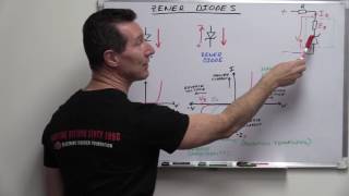
- Circuit building block time. The capacitance multiplier and how it gives almost negligible power supply ripple compared to a voltage regulator.
Whiteboard theory and then some bench demonstrations and experiments. Plus a twist at the end that proves that the "Capacitance multiplier" is perhaps one of the most mis-named circuits of all time.
Forum: www.eevblog.com/forum/blog/eev...
EEVblog Main Web Site: www.eevblog.com
The 2nd EEVblog Channel: / eevblog2
Support the EEVblog through Patreon!
/ eevblog
Stuff I recommend:
kit.com/EEVblog/
Donate With Bitcoin & Other Crypto Currencies!
www.eevblog.com/crypto-currency/
T-Shirts: teespring.com/stores/eevblog
Likecoin - Coins for Likes: likecoin.pro/@eevblog/dil9/hcq3
💗 Likecoin - Coins for Likes: likecoin.pro/@eevblog/dil9/hcq3 - Věda a technologie


![[柴犬ASMR]曼玉Manyu&小白Bai 毛发护理Spa asmr](http://i.ytimg.com/vi/0TsXQ7z2Dh4/mqdefault.jpg)


Brilliant, Dave. Wish you did more of this content. Bring back fundamentals Friday!
Totally Agree!
i love fundamentals friday. and mailbox monday. i liked when the segments were on days of the week. i found it easier to get the content i liked and stuff. cos i get in different eevblog submoods.
Second that motion!
Neat.
I resubscribed after watching this video. Bring back fundamental fridays.
I don't think the phrase "Half a bee's dick" has gotten NEARLY as much use as it deserves
Then again, bee's dicks are enormous compared to body size. Drones are quite a bit bigger, and most of that actually is for the phallus that is extended when needed.
I also vote +1 for „winner winner chicken dinner“!
Wow, this video just saved my ass... I had 350mv ripple on a crappy power supply at work and it was messing with some of my testing and this circuit got rid of it all! Thanks so much Dave! You're a real life saver!
Nice!
@YiZhou Wang You still depend on a voltage regulator. The V+ going into the capacitance multiplier comes from a regulated source.
@YiZhou Wang if the power supply's hackablr enough, one could replace its feedback circuit(probably a voltage divider) with one placed after the capacitance multiplier
YiZhou Wang yo, he specifically states that should one require stable output voltage, then one should use a Voltage regulator
Most inexpensive ( yea right!) power supplies simply use a parallel electrolytic capacitor as a filter to reduce ripple. The best filter is an inductive pi filter. It consists of, in parallel, of a capacitor, a series inductor, and another parallel capacitor. It looks on a schematic like the Greek letter pi. This takes of capacitive and inductive ripple. It precedes a linear or switching power supply.
Frank
Thanks, Dave, for all your efforts. I retired in 2013 after 34 years on the road in the US and Canada as a Biomedical Field Service Engineer. Like many old guys, I have a pretty decent wood shop, but I got to looking at my pile of electronics stuff, collecting drifts of sawdust, and decided to get back into it. Your videos are a great help, renewing what I used to know, and learning new stuff as well. A great help in keeping the old brain cells moving.
I am aiming for the same job, if you have any advices for me I'll be glad.
This type of video, where one "building block" is explained in detail is my favorite.
@EEVblog Hey Dave, I LOVE your videos! Hands-down... the best in electronics on CZcams! I benched this circuit IDENTICALLY as shown including values for components. (I even used a mini breadboard) to DUPLICATE “EXACTLY” what you used in the video. I used a Switch Mode Power Supply configured for 5v. (Just as you showed in the video). However, I couldn’t replicate your ripple results.
COMPONENTS:
Switch Mode Power Supply Volts: 5.00 (5.001v Actual Output) - Measured using:
Keysight 3458A - 30min+ warm-up
Keysight U1271A
R1 (Base Resistor) = 1k - 1/2watt - 1% (996.83 Actual) - Measured using:
Siglent SDM3055 - recently calibrated - 30min+ warm-up
Keysight 3458A - 30min+ warm-up
C1 = 470uF 35v (486uF Actual) - Measured using:
Siglent SDM3055 - recently calibrated - 30min+ warm-up
Keysight U1271A
RL (Load Resistor) = 270 - 1/2watt - 1% (269.94 Actual) - Measured using:
Siglent SDM3055 - recently calibrated - 30min+ warm-up
Keysight U1271A
Q1 = BD137 - (not a BD137G)
-------------------------------------------------------------------------------------------------------------------------
BD137:
R1 Voltage = 57.593mV = 0.057593v (Verified with the above 3 Multimeters)
RL Voltage = 4.2747v (Verified with the above 3 Multimeters)
I1 = 57.78uA = .00005778A
IL = 15.83mA = .01583574A
hFE: 274.069574
Of course, it smoothed out the ripple nicely. However, my ripple numbers are considerably higher than yours. I used a Keysight DSOX2012A to take the measurements. (Essentially the same O-Scope you used in your video). - I wish we had the ability to attach photos here on CZcams. One thing I would like to point out that when I measured, I used a ‘M’ BNC Oscilloscope Probe Adapter & a “Pomona” ‘F’ BNC to Banana-to-Hook Test Leads on the Oscilloscope Probe. This is the best possible connection to give the “FAIREST” test possible so that external Transients were not introduced and won’t skew the measurements. This is why I didn’t use the supplied Oscilloscope Probe “Ground Wire” to Alligator clip.
Ripple PRIOR: (Raw Power Supply output)
Pk-Pk: 40.92mV
Ripple w / “Capacitance Multiplier”:
Base Resistor R1 = 1k (996.83 Actual)
Pk-Pk: 17.64mV
Base Resistor R1 = 10k (10080 Actual)
Pk-Pk: 36.17mV (Pk-Pk went up, (by DOUBLE) NOT Down)
Using the EXACTLY the same parts & essentially the same oscilloscope to take the measurements, how were you able to reduce the Ripple down to: ~ 2.5mV Pk-Pk? Something doesn’t add-up here.
BTW, I agree with you, I don't like the term "Capacitance Multiplier" either. It's really just an RC Filter.
Nice explanation, Dave. There is a trap for young players here. If the input voltage ripple amplitude exceeds Vbe-Vce~=0.6V, this circuit doesn't work properly anymore, because the collector voltage drops too close or even below the emitter voltage. At that point, only the base current makes it to the output and there is no current gain anymore. An additional resistor across the capacitor can be used as a voltage divider to solve this issue. This will lower the base voltage, which lowers the emitter voltage, and allows the input voltage to drop lower before there is no current flowing from the collector to the emitter. I ran into this problem with a low power, high voltage boost converter that had more than a volt of ripple.
yeah, I was kind of thinking about that, and wondering if putting a cap on the output would even make any diff at all other than smoothing out the current draw of the load through the bypass transistor. and, at that, what is preventing that second resistor in the divider, from being a simple zener, to further stabilize the voltage of the output. I guess it mostly depends on what the load is, and what the supply is doing. lol.
I also found, for many low power things, a simple in-line diode with a cap after it was sufficient for a single device without trying to stabilize an entire power buss just for a single chip to be happy.
Does this still occur if I were to use a darlington pair?
@@ninethirtyone4264 I think this is getting even worse, because the voltage drop is even bigger, about two times the voltage drop of a normal BJT.
Does this happen with a mosfet?
Paul Max Avalos Aguilar : Actually, with MOSFET, you have the threshold gate voltage lost necessary to turn the MFT on. Which is typically in the range of 2 to 6 Volts. This value would be the "room" available for ripple elimination. The hick with MFT is that this threshold gate V significantly vary with Source current, so this would create a situation where you would loose even more voltage than with a BJT. The advantage though is a better ripple filtering than with BJT, as long as your initial ripple is lower than V gate.
For years I have been using 3 different names for this circuit among my colleagues.
1. Capacitor Clipper
2. Ripple Clipper
and my personal favourite:
3. Ripple Cripple (May not pass PC 'certification')
Dave is a knowledgeable teacher. This is one of his more direct and precise tutorials. Informative and enjoyable.
we usually just hire an intern to watch the scope with one hand on the regulator's Vout control. They've gotta have good reflexes though. And coffee.
Glad you're still doing these. They're fantastic.
s. 578 in The Art of Electronics :)
And if the ripple is in the MHz range, you can add a ferrite bead to the base lead of the transistor.
Thanks
s.578 - you are german!
Chapter 8.15.1! :D
he could be turkish too
Why the base? Why not the emitter? The current coming from the base is very minimal compared to that moving from the collector to the emitter? Can you please explain this maybe im missing something here thanks
In the '90s Technics (then Matsushita Electric, today Panasonic) called a variant of this topology "Virtual Battery", claiming a supply to analog stages almost as clean as a battery. They used a big cap and a mosfet, and there was a switch in place of the resistor. It was used in their HiFi components.A very simple idea, but it does in fact work fine.
Hi Dave,great video.
I used to service electronic engine analysers many, many years ago.
One brand of analyser, proudly made in Sydney, use the capacitor multiplier in its pos and neg supplies to the scope display.
They used a 15inch TV B/W picture tube with magnetic deflection. The scope did not run at TV scan frequencies but swept at 10Hz up to over 1kHz. So the load caused by the deflection circuitry, apart from being quite large, was also not of constant frequency.
The multiplier circuit work a treat and was made up of 4700uF and good old 2N3055 and MJ2955.
The fundamental content videos are always nice, thanks for showing!
12:30 - This circuit also provides a soft-start as C charges on power-up
Hands down the most informative long-term active channel with both great insight in complicated stuff but also content for a beginner like me.
So good you could do one for each day of the week. Methodical Monday, Tuition Tuesday, Whiteboard Wednesday, Theory Thursday, Fundamentals Friday, Strap in Saturday and Sod off it's Sunday. Thanks for all the great content.
Strap on Saturday? Oh shit, my eyes are playing tricks on me again
@@mr-meek hehe. Yours is better.
Great video Dave! Your building block circuit tutorials have been a tremendous help to me.
AWSOME tutorial. Love this content. Practical, easy to test at home and above all genuinely useful for so many applications.
Great description Dave! In the "old days" we called that a ripple stripper, not a capacitor multiplier.
I used these (BJT implementation) for the power supply rails feeding VCOs in PLL synthesizer applications many years ago to reduce oscillator modulation due to power supply rail ripple/noise, thus improving phase noise in the design situation.
Great info as always, and Dave's colloquialisms always give me a chuckle.
That's the best and most visual explanation of the Capacitance Multiplier i have seen so far.
In telephony, this circuit ( Rb, C, Darlington Q, and Re) are used as an "electronic inductor." (Re is the load resistor - RL in Dave's circuit). If you measure *AC* impedance from V+ to ground, (or do the math for this circuit) you'll find that at low frequencies, this impedance is Re - which is typically small. At high frequencies, the impedance is Rb, which is larger. In-between, the impedance goes up at 20db/decade - the same slope as an inductor.
This assumes you are below the frequency where Miller capacitance is a problem - above that frequency, the impedance will start dropping again.
This circuit was used to replace the inductance of the ringer coil when newer phones came out. The phone lines were specified to require a certain amount of inductance across the leads when on-hook. When big mechanical ringers were replaced with electronic ones, they still had to keep that inductance in the circuit - hence the "electronic inductor" circuit came to be. The effective inductance of this circuit only needed to appear in the audio band.
When using this circuit for ripple reduction, I've heard it referred to as a "rip-red," i.e. short for "ripple reducer." In that case, Re is replaced with the load you're reducing the ripple to.
Would that make it a form of a "Gyrator" circtuit?
en.wikipedia.org/wiki/Gyrator
👍 great info
EEVblog one of the best on youtube, excelent !!!
You are a very good teacher taking all aspects as examples, why things not always goes together. Excellent!
You forgot to mention that the output of the emmiter follower will be at least 1 x vbe lower or 2 x vbe for a darlington.
You may need a diode to protect the gate and discharge the capacitor when the supply is turned off
I once did the opposite: an active capacitance cancellation circuit. I used it to cancel the capacitance of a photodiode so that it could run faster as a data receiver. Without the circuit, the bandwidth was limited to 200Hz. With the circuit, I could get the required 32kHz. It was a long range infrared remote control receiver.
If you still remember, how did you make such a circuit? Could you make a schematic and brief theory of operation?
It's been decades and I no longer have access to the schematic, but as I recall, I used an op-amp as a non-inverting amplifier. The anode of the photodiode was connected to the input and the output of the amplifier was connected to the cathode. Zero bias was maintained across photodiode with the output tracking the generated voltage. Response went from DC to whatever the op-amp could muster. There would have to be some bias on the op-amp input. I believe that it was a large value resistance to ground, although you could also use a voltage divider. The circuit easily received from a near-infrared LED (900 nM) 100 ft. away. The idea wasn't mine. I got it from a trade magazine article that I probably couldn't find to save my life. Chances are, it's out there somewhere. The company that I designed the circuit for no longer sells that item.@@milesprower6641
Sounds to me like bootstrapping. You can do the same thing to present very high input impedance to a piezo pickup. There's an article on Elliott sound that gives an example. It's a good trick, you just have to watch out for boosted low frequency response.
I can’t thank you enough! Sharing your knowledge is such a big a gift to the EE community.
Electronics :)
Every time I watch one of your educational videos its like the sun shines on my brain and the fog clears immediately. Thanks so much
Great explanation Dave! These video's I enjoy the most next to your teardown vids.
Smashing video dave :-D
I've seen this configuration a lot in basic linear power supplys, but never thought too deep about the filter magnifier effect.
A handy ripple reducer as long as you don't mind a bit of voltage loss :-).
that "I only give Negative feedback" on your T-shirt is epic
Just from 10 your videos, I have learned way more about electronics than I did in my entire lifetime, including the university. Thank you.
These kind of videos are pure gold.
Thanks Dave! Even after getting my BS, your fundamentals videos continue to educate. School can't cover everything :)
I've found myself kind of accidentally in communications research at the moment, so at this point I'm not really advancing my circuits knowledge outside my free time! I need to dedicate more time to DIY electronics fiddling.
It's 4:30 in the morning.. I was wasting hours of searching through many of powerful linear regulators.. But all too expensive and space consuming... I also really needed a soft start feature too. I was close to alcoholism, but then a saw this video, now I'm in love with you!
I love extrapolation of different topologies and calculating transfer characteristics. Good video Dave.
Very interesting circut, have spent 40 years in electronics engineering and this is new to me. Thanks!
its a really smart way of making your SMPS "linear". Probably a nice solution for compact audio amps and lab psus.
Exactly that. It's very popular. You just need a little higher voltage PSU then normally.
This was a very interesting video that I really enjoyed. Thank you for sharing. Personally, it would have been nice to see the MOSFET in action as well!
Another super video from Dave ! Thank you for your contributions to our understanding of electronic circuitry.
That was super useful, thanks Dave. I was just messing about with a similar circuit and the ripple from the input was getting magnified by the output. Now I have a way of figuring out how to filter that mess.
Brilliant, thanks Dave..... Love these fundamentals..... Useful circuit.....
I can't find the link of the full demonstration video of regulator voltage you mentioned
I love all your videos !!
Fundamentals videos like this are what drew me to the channel and caused me to subscribe. They are very helpful for the hobbyist.
One of the best instructors I have seen..!! You keep it interesting and moving at a good clip..!! Great stuff..!!
You're a very good teacher. :-)
26:00, the Op Amp also has its own power supply rejection ratio, if its positive supply is the same ripple injected power supply going into the multiplier, then the ripple rejection will only be as good as the op amp's PSRR.
Your videos are amazing. I know that but I love watching Dave explain stuff
Awesome! Love your circuit demos! I learn a lot with them.
Actually it should be called a load multiplier. The effective load value that appears parallel with the capacitor is beta×output load. That is why it is very effective as a ripple filter. I actually used something like this in a car audio application to filter alternator ripple to a car audio power amp. You could hear the alternator ripple comming through the speakers as you reved the engine; additional to the capacitor I used a 12V zener in parallel. Generally the alternator ripple is riding above 12V.
Dave , you're the man 👍
I'm so happy you just stream right to my bench to drop off new practices with that clever shirt. Right as I'm designing power supplies. What a day to live. Its no Free Energy but I'll take it! Thanks Dave
Dave for president!
Your video's are a great contribution for the community. Your cheerful tone is a nice gift for every one.
Excellent tutorial Dave... Been a while since you did one.... We need more.
Ok. I gave it a try and it worked, but there was a significant voltage loss with a 1k R. Using a smaller R raised the voltage back, but the ripple also returned. Any suggestions?
For one reason or another, I forgot this circuit! Genius! Thank you!
Thanks, this is just what I needed to think about for the dual charge pump circuit I'm working on!
NPN transistors for the win!
I clicked like on this just because it's Fran.
Me too, just got her Franlab T-shirt
I am a big time Fran-Fan u know. Good to see you here Fran.
That was interesting Dave hope u keep posting such fundamental videos.
A mosfet or igbt depending on the amount of current/voltage u need then clamping the gate voltage with a zener diode then another low pass filter will do well
60fps, a real whiteboard, good old Dave. More this :)
its like watching Horowitz and Hill the movie, my all time favourite electronics manual in video form. Love this stuff Dave.
Excellent video! You can explain hard topics in very clearly way. Please make more videos like this one!
I really missed these videos! And well... that was (maybe?) new to me, naming is indeed as you said tricky... It makes sense though, plus the transistor as a primarily a current source has a really high noise rejection by itself... Yeah! Cool stuff! BTW... I really don´t get why it would work with a MOSFET, you have to run it in the non linear region and it would be rather messy.
MOSFET could get messy, so I didn't go into that. You can use one though.
You know, I was giving it some thought and what confused me was the DaveCad layout. Yeah that´s practically an emitter follower but you are saturating the transistor. Saturated stuff generally not behave well especially with AC. What if you replace that resistor with a divider, depending on the transistor the drop you aim for isn´t that big (0.2 - 0.5 of a volt for a BJT) and you anyhow accept that you´ll have some voltage drop there. You can still calculate everything easily with Thevenin equivalent resistor for the divider. And you´ll have the transistor operating in the linear region which makes it a current source which in AC is an open circuit (of course you´ll still have noise coupled from the capacitances of the transistor but that might be more manageable). And yeah you´ll be burning power on that transistor a bit more from your suggested citcuit, but when noise is the problem and you only power an op-amp or two. Well, that might be a better solution. I haven´t tried it though to see the difference, but I know why it reminded me something. I hope you see it and give a reply, or why not make a follow up video! Cheers, mate!
Eh? Well that sounds awfully a lot like a regulator :-P
Yeah, that's why people invented IGBT's :) You could use MOSFETs in such cases, no problem, really. But IGBTs at least will heat up twice less :)
The MOSFET will inherently work in the saturated region. At low frequencies, the gate voltage will be the same as the drain voltage. This configuration is called a diode-connected transistor, and it assures saturated conditions (with Vgs=Vds and Vgs>Vth, you will always get Vds>Vgs-Vth). Since the current at the gate of the MOSFET transistor is virtually zero, higher resistance values can be used. The voltage drop of this circuit will be close to the threshold voltage of the MOSFET (Vth). Use lower Vth transistors for a lower drop. At higher frequencies, the voltage at the gate will drop to zero. If the transistor you are using has almost zero channel effect, then the voltage at the drain will have almost zero impact on the drain current, hence zero voltage gain from the input to the output. I think this will work neat with a MOSFET.
Basically good facts all along. You even showed that the breakpoint frequency did not change as expected. But your move from passive to boosted solution left a bit of a gap in cost/benefit respect.
Too bad, the low drop-out regulator is the one that has miserable input ripple rejection. But guess what - the current booster is no better if the voltage head is lost. As you talked about the 300 mV drop on the regulator case, you did not emphasize that single emitter follower has some 0.6 to 0.7 V drop, depending on load. A Darlington tends to have 1.4 V drop. A “Fetlington”, i.e 2N7000 has about the same threshold voltage and big MOS FETs 4 to 8 V. You could do better with depletion mode FETs, but that is already pushing the state of the art.
Traditional voltage regulators when given enough head voltage do a decent job in reducing ripple. But if the input is for example 8 V peak and 7 V ripple bottom, even the traditional 5 V output regulators are at the spec limit. The 2 V head requirement is counted from the ripple bottom...
So can I understand that this circuit is just for using not ridiculous value of R and C, but no improvement of cutoff frequency, right?
Learned something again, thanks Dave. Great stuff.
An emitter follower with large bypass capacitance at its base and emitter (presumably this circuit would have bypass cap at its output) can be prone to RF oscillation due to stray series inductance if not laid out very carefully. It wouldn't hurt to add an extra SMALL resistor (like 10 ohms) in series with the base to suppress such oscillation.
What power does a fet or bjt dissipate in this circuit ? Just the ripple voltage x current or are there more factors than internal resistance / wiring.
Basically the input-output voltage drop multiplied by the load current
0.6V times current. A small price to pay in low power applications (below 10A or so).
You may look for lower dropout device, however you have to make room for the ripple, so your drop has to be higher than ripple Vpp+0.2V or so.
Nice! Could we use LC filter instead of RC?
yes it works better but is more expensive and takes more space
Wou, so much enthusiasm and delight. I love this video.
Thanks - reminds me of the early days of eevblog - great value . “ the best form of marketing is education “
The Sziklai pair is pronounced like "sick lie"... Sziklai, not slikai. And its benefit is, you're only dealing with a single Vbe drop (and the Vce drop, much lower at saturation, of the other device). Also, it generally performs better than the Darlington in most applications, but it's more expensive to produce monolithically (lateral PNPs in a standard cheap bipolar process is pretty much a no-no, so you need a much more expensive complementary process), hence why you don't see NPN/PNP-type Sziklai pair devices floating around Digikey.
Other advantage in series pass elements is that you drive the base via a pull-down resistor rather than pull-up, so it doesn't run out of drive as Vout approaches Vin. Of course you need a third transistor as an error amp though. Still, a very effective regulator for a reasonable parts count, and will easily outclass the typical IC reg for ripple rejection.
It's the first time I've ever heard anyone try to pronounce Sziklai before :) I usually wimp out and call them "Compound Follower Pairs"
I've seen complementary feedback pair
yep or that :)
Im not a fan of them in power amplifiers. Too many stability issues. Triple darlington is better.
Depends. Sziklai pairs are typically associated with less distortion than the Darlington pair (or the "Trarlington", as Bob Pease called the triple Darlington configuration). And of course, better thermal stability, since the V(be)s of the complementary devices move in opposite directions. That means less ballasting in, say, AB configurations, and therefore, a simpler and nicer design with more output swing and the slight noise contributions of larger ballisting resistors.
And finally, let's not forget the bandwidth issues of the Darlington, which are again lessened with the Sziklai configuration ;-)
You could always add a zener diode in parallel with the capacitor, then you will have basic voltage regulation, sure it's not the best but for most cases it works well enough.
Maybe combine that with a series pass transistor to lower the ripple even further?
sorry, I guess thats exacly what you meant 8-)
It's all a question of how much power you can burn to regulate the voltage and stabilize the ripple. The larger the heat and power budget the simpler the design.
Main issue with a parallel zener is that the cap multiplier only has a volt or two drop from input to output. Thus, the zener current will vary wildly with small changes of Vin. Likely, a resistor value that gives enough zener current at min Vin will cook the thing at max Vin.
The pure cap multiplier doesn't have this problem because output tracks input.
I enjoy your tutorial videos very much and hope you decide to get back into those. You are a gifted teacher
Thanks Dave. It's good to have an ace up sleeve like this.
"Active low pass filter" sounds better than "capacitance multiplier"
Inductor + capacitor instead of resistor + capacitor. Really effective.
Yeah, the filter pole isn't really sensitive to the beta gain of the transistor. It just allows you to use a bigger resistor in the LPF, i.e. lower capacitance for the same RC time constant.
The only thing is that voltage drop is really high, which compromises the efficiency of DCDC converter
Great video. When you were discussing the transistor/ Darlington current amplifier, my first thought was, why not use an op amp. I am happy that you discussed this at the end.
Bob
I'm not at this level yet, so I don't really understand what you're saying, but this video is still great to watch! You're so stoked about this!
Can you go over charge pumps next?
He did in several earlier video's.
#469 #473 #483
What even works better is a RCRC network because you actively make a 2nd order filter (Q=0.5). Another method is forming a 2nd order sallen-key with a transistor.
That's at 13:20 :)
railspony . Correct but he only describes it very briefly not even mentioning that the slope of the filter doubles. This is particularly useful in situations were you need to get rid off high frequency stuff. Something that's not even really mentioned.
Learned something new today! I have some sensitive things I'm trying to drive with a DC-DC converter and hi-freq ripple is killing me. This made my day!
I became a cropper trying to use a linear regulator to remove the ripple on a DCDC converter, only to find that the PSRR for the reg wasn't as high at the frequencies of the DCDC switching. This circuit might just be a solution! Cheers Dave!
but how does it perform under a LOAD?
"Half a bees dick" LMFAO! That great! Another great engineering lesson.
Thank you Dave. Just what I've been looking for after days of internet searches including looking at expensive bulky Pi filters.
awesome tutorial,
Thank you Dave and DaveCad
You can make it into a voltage regulator at the same time by adding a zener diode from base to ground.
Ripple current reduction happens by amplifying ΔIb by β and subtracting from ΔIc. The ripple waveform at the base is almost symmetrical to ΔIc
and is 180 deg out of phase by RC charge/discharge action. If you replace C with a zener your ΔIb will no longer be a symmetrical waveform to ΔIc
and the effect of reducing the ripple will be lost.
Rob he didn’t mean replace c but add a diode
How the hell youtube know Im dealing with that right now ?
Thanks for covering this, first time hearing of this topology, really cool!
I like your description of the circuit in terms of blocks.
so why not use an inductor instead of the resistor... ?
+Theo Size and cost of the inductor, if your power supply is for vacuum tube audio. Values of 3 to 10 henries, often in double pi configuration, are used in tube audio.
I really don't have any experience with vacuum tubes, but yeah, 3 H are insanely high value.
But let' s say we want to supply 5 V to our electronics ICs, or to a load that cannot tolerate high ripple. For fc = 1.6 kHz and Cf = 100μF, the value of the inductor is 100 μH, which is totally doable. Anyway, I will test it.
Hmm, LC resonance is an issue, so more care is needed designing it.
Have a play around in a circuit simulator like LTspice. It will let you see what happens for all kinds of values. I was just exploring RC filters and inductor filters. You have to be careful with LC filters so that they don't turn into tank circuits ring and oscillate and can drive the output voltage way out from where you wanted it. It can be made stable and work well as a ripple filter, but some changes to the downstream capacitance can affect the output in non-intuitive ways, so one may have to re-characterize the circuit to make sure it's behavior is known for all possible input scenarios (or close to, you can't know everything).
Theo transistor hate inductor. and for lower cutoff frequency, your inductor will be super duper big.
I wouldn't exactly call ~35dB (4:24) a _"horrible"_ (4:45) reduction.
The graph is showing how PSRR reduces with voltage across the LDO. The 35dB PSRR you mention is at >1.5V dropout across an LDO. That's a pretty generous dropout voltage for an LDO. At 0.4V dropout it's around 27dB which still isn't bad but shows the point he's making that it reduces with voltage drop. At less than this, it falls off sharply and you wouldn't want to operate in this region if your input has much ripple, even if the datasheet headline claims e.g. "a low dropout voltage of just 17mV". The reduction of PSRR with frequency is generally more of a problem as the ripple from DC-DC converters is usually in the order of 100kHz to a couple of MHz.
Check the frequency...
OK that particular chart for that LDO was at 100kHz. Fine, but what's it like at 1MHz? Can I assume it's similar to that chart? I don't know what LDO that was from, but as you overlaid text in the video (4:35), you know it changes with frequency. If you look at the datasheet for the MCP1700, the Electrical Characteristics table says -40dB PSRR *(at 100Hz)*, but if you look at the PSRR vs frequency plots (fig 2.14 and 2.15), it's about -25dB at 1kHz, -10dB at 10kHz and 0dB at 100kHz. That's a far more dramatic change than the -35dB at 1.5V drop vs -27dB at 0.4V drop in the chart at 4:24, that's my only point. You have to be careful shopping for LDOs if you need good ripple rejection that it will work adequately at the frequency you need.
Dave I have the early stages of dementia and you should have lost me in the first 5-10 minutes of the video, but had me right up to the end m8. That speaks volumes about the effectiveness of your teaching. This was nothing short of fascinating, and as it happens it's a small piece of the puzzle I'm trying to figure out and put together in a correct way so that it actually works. Liked and Subscribed sir. Thank you.
Thanks for this great tutorial. I just posted on the EEVBlog forum a sample schematic of my stereo preamp which I had to repair last year. It has the same circuit configuration you showed. This very transistor died on one channel and I never quite understood why it was there. Now I do :)
This circuit can't filter out ripples higher then voltage drop across transistor.
You’re free to increase that drop. In other words: use the capacitor to lower the impedance of a Zener diode :)
The capacitance is multiplied, but the resistance is divided, having no net effect on frequency response
Nice tip, great demonstrations and awesome explanations! I was also missing these basic electronics videos ;). Excited to try it this weekend :D
Thanks so much, a very informative and practical video. I came across some similar problems recently which gave me lots of headache.