Wire Analog 4-20mA to 0-10VDC inputs of Micro820 PLC and scale

Vložit
- čas přidán 9. 07. 2024
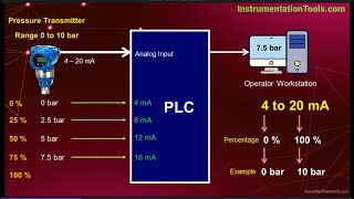
- In this video we are going to show you how to wire 4-20mA sensors to the built in 0-10VDC inputs of an Allen Bradley Micro820 PLC using load resistors and scale them in Rockwell Automation's Connected Components Workbench software. Using Ohms law, we can convert the 4-20mA reading across the load resistor of the Micro820 PLC to a voltage reading.
View the entire Micro800 Connected Components Workbench lesson series at twcontrols.com/micro800-conne...
Items used in this video:
PLC Trainer twcontrols.com/plc-trainers
The above links make these videos possible. Please use them!
Support these videos while you advance your skills courses.twcontrols.com/ - Věda a technologie


Thanks for watching! If you are looking for the complete Connected Components Workbench PLC Training series, visit twcontrols.com/micro800-connected-components-workbench-lessons
Tim you are the freaking best in CZcams, how can I support your channel?
Your comments are enough, thanks! 🔥
@TimWilborn, these videos are awesome. I'm a 20 year C/C++ veteran getting back into PLC programming and your videos are making so easy for me to look like a rockstar ("How did you figure this CCW thing so fast!?"). Thank you, thank you.
I'm glad to help. CCW does have some learning curve but it has become a very good platform.
These are so helpful! Thank you!
You're so welcome!
Thank you. This couldn't have come at a better time.
Glad to hear it Jason. We're going to go through how to limit the range of the analog signals tomorrow.
Tim - your going to make me money! thank you sir!
Tim, me acabas de salvar la vida. Muchas gracias por esos excelentes videos te recomiendo sigas así.
Saludos desde México.
¡De nada!
Tim, I dont make comments often. Like this is my 3rd in my whole life. But I'm commenting because you seem like a good fella and your vids are proper helpful. Thanks mate
Thank you so much for your compliments Matt!
Hi Tim, you're videos have been extremely helpful for students like me. Keep it up! Thank you so much.
Happy to hear that!
One of your best, Tim! Please touch on why 4-20 is used way more than 0-16. Thanks!
Thanks Jack! Check out around 4:30 of this video for why we do 4-20mA as opposed to 0-16mA or 0-20mA. It is called a live zero. czcams.com/video/GrIZApDo2MQ/video.html
Thank you for the videos. What is the best way to introduce an offset to the output of the SCALER? For example, if my SCALER Output is displaying 0.5 when it should be 0.0.
Use a subscribe instruction directly behind it.
Hey Tim, love your videos. Just a question when you a dividing the raw unit in half for the scaling you divide 4095 in half to get 2047.5, but wouldn't you count zero as a number? so 0-2047 and 2048-4095 would be equally divided in two so you could just put 2047 in the scaler? Just wondering if I'm up the wrong tree here. Keep up the good work.
I noticed something when I tried this. When I would go online and run the analog sim up to 20ma, the engineering value in the tag slowly dropped. Meaning: usually the value will bounce around but for some reason the value dropped very gradually from bouncing around 28300 to bouncing around 28200. If these numbers confuse you, I was using an 2080 IF2 and also only had a 220 ohm resister so the math was a little different.
With an IF2, you wouldn't need the resistor. Just select 4-20mA in your configuration and wire accordingly. Check out this video. It is for the IF4 but would be similar.
czcams.com/video/z3SOxTDLHb4/video.html
@@TimWilborne
I know that the if2 can be used as a 4 to 20 mA. I was just trying to practice converting 0 to 10 into mA. Just thought it was odd that the upper value seem to be bleeding down and was wondering if you’ve ever heard of anything like that happening before?
Tim, I love your videos!!! I was wondering if you could do one on an RTD plug in. I am used to setting an RTD up on RSLogix 500, but for some reason I am super lost on this platform
Here is one on installing plug in modules. It is for 4-20mA inputs and outputs but it should get you close.
twcontrols.com/lessons/allen-bradley-micro800-plug-in-module-configuration-for-the-micro820-micro830-micro850-micro870
Hey Tim, thanks for all the help you provide to us students, its truly invaluable. I'm currently using one of the Micro820 trainers and am trying to scale the 0-10V Analog input to the Voltmeter analog output. I just cant seem to figure out how to get the Analog output to work with the scaler. I appreciate any help or advice you have to offer. I'm used to RsLogix500 and CCW is pretty new to me .
Never mind Tim! I figured out that I had to use an ANY to WORD instruction to convert the output from REAL to a WORD. Thanks again for your videos, me and my classmates at NIC really appreciate you!
Yep, the ANY_TO instructions are a must learn! Glad you figured it out.
Thank you for your videos..but please do you have a circuit diagram for the wiring in this video
No, I don't believe we have a sample of this one but it is pretty straight forward in the video. What is tripping you up?
Hey Tim, I was wondering if you could explain when best to use a local variable versus a global variable? Thanks!
Hi Brody, yes that one is on the list!
Tim
Do you have a video on how to convert 0 to 10 volts to 4 to 20 ma ???.
Thanks.
No, you'll need a converter to do that.
Hi Tim, thank I you for your videos. I am using a micro 850 to build a control system as part of my final year university project and your videos have been the saving grace in helping me figure out this project.
I did have a question that I am hoping someone could help with. Is there any over voltage protection on the 2080-IF4 face mount modules? I have looked on line and found nothing after many hours of searching. My interest is in preventing damage to the module should the pot in the potential divider circuit be damage and the full 24 volts be see by the analog input pin. I have had a pot fail during installation and I would rather build a voltage clamping circuit to protect the module if it does not already have over voltage protection.
Check the specs but 24VDC will likely damage the IF4.
@@TimWilborne Thank you Tim. I built a 10VDC regulator circuit to supply the potentiometers which holds the voltage stable even if something should go wrong with the pot.
Thank you so much
@@stomp1691 What did you end up building, I completely forgot I had this video on it 😂
czcams.com/video/A0eIHWvyZEg/video.html
Hi Tim, I used a LM317 to build a regulated 10 volt output to use across my 10k pots. It also solves the problem of voltage dips when all the various loads cause voltage dips from my main 24Vdc supply. It makes for very stable analog inputs to the plc... and I haven't blown my input pin which is great.
I’ve got an 820 where we use the add on 2080-if4 analog input card. A 4-20mA temperature sensor failed and all I have in stock is an RTD with a 2 wire 4-20mA puck that takes a max 30vdc input.
When I calibrate the transducer I confirm my ma signal across full scale then connect to the input card the signal (at -15 deg) displays full scale 122 deg because the input is 27mA. I confirmed this with 2 transducers and both transducers work on test bench to a ControlLogix analog input card.
Not sure if my transducer will run on 10v and I don’t have a spare analog card to test as I don’t want to risk blowing anything up at 24v. Do you think this will work to bring my signal to a voltage input?
What voltage were you running to your analog device?
Since it says a max of 30VDC, you should be good with 24VDC. Here is an upcoming video that will help you with your wiring. You will likely be connecting it in 2 wire mode.
czcams.com/video/k8_axizTWTE/video.html
Hi Tim! Is there any way to stabilize the values of variable AnalogMaScaled? The decimal places vary too much, which is a problem for me, as I need to work with precision.Thanks!
I am surprised that I have never done a video on this...here you go...
FV=FV+C(NV-FV)
Where:
FV= Filtered value
C= constant (range 0-1) The smaller the number the more dampening.
NV= New Value
Filtered Value= Filtered Value+Constant*(New Value-Filtered Value)
New Value = Unfiltered Value
Constant= 0.00-1.00 The smaller the number the more damping.
How to convert 4 word data change to single real data
Tim,I have a pressure transducer 4-20 ma 0-100 psi. How do I scale to measure feet? I would like to open a valve at 26 feet and close the valve at 32 feet. Can you point me in the right direction?
There are 2.31 ft per PSI, so your range would be 0-231 ft.
Hi i just want to ask if the sensor that has 0-5V output are posible to use in the plc that require 0-10V analog input.
Yes, you would just utilize half of it's range
Thank you very much for your reply sir.
Will ths or something similar work on the output ?
No, you would need to use a voltage to current signal converter.
I'm trying to figure out the principle operation of 4-20mA signal. Lets say, we have a RTD sensor and wanna get input on a PLC I/O inputs which take 0-10VDC. If we connect on the current loop a resistor (in order to convert the signal and take the voltage measurement for PLC), that's may cause drop voltage, and therefore, current flow restriction. Obviously the restriction depends on the value of the resistor. SO, how is that possible to get 4-20 mA constant current on our loop, without its resistor affects the current in our circuit?
An RTD sensor needs to be connected to an RTD input. You can't simply feed it voltage and read the voltage drop across it.
Your question is a common one and shows you are thinking !! Heres what happens ... the transducer ( pressure, temp, etc to 4 -20 ma) is scaled so that it will produce the desired loop current , over a range of loop resistances. The adding of the 250 ohm load , does in fact cause a brief reduction in loop current, but the transducer will correct this by in effect lowering its resistance to bring the current level back to the original value.....if the loop has for example a 24 volt power supply, the total loop resistance is limited to r= 24v /20 ma ohms, so you could even add a few more 250 ohm resistors in series before the transducer could not supply the 20 ma loop current..
Hi Tim, I have a Balluff BUS series analog input/digital output sensor. I can’t figure out how to set it up in studio 5000. I have this sensor being used my a proprietary PLC in my plant but it’s connected to a Bekoff plc. In that instance it measures distance. In the Input card, the white wire is in the signal, and then brown and blue is power. I tried to set it up this way in studio 5k but I’m getting some weird numbers. I’m using a Flex analog card btw. When I put my hand in front of sensor, it will go from 32000 to 10000 to 8, etc. I can’t get it to measure from 32000 to 0. Can you figure out what I’m doing wrong. In the analog card properties, I’m using 4to20 milliamperes.
What is the part number of your input card?
@@TimWilborne flex ie8
@@TimWilborne FLEX IO 1794-1e8
Hi Tim.
I would like you to take me a doubt I'm with an analog card 2080_OF2 (micro850) your output from 4 to 20ma is connected to the input of Powerflex525. I used a scaler block but the values came out different than when I use the direct signal generator on the Inverter input. Why does it happen?
Analog Signal Generator Card
20ma = 100hz 20ma = 100hz
16ma = 67hz 16ma = 75hz
12ma = 34hz 12ma = 50hz
8ma = 11hz 8ma = 25hz
4 ma = 0hz 4 ma = 0hz
Thanks Tim. And keep on with the best youtube automation channel and content
Are you sure you have it configured correctly for mA?
@@TimWilborne I think so. I'm using a block scaler writing a value from 0 to 100 in the input. Input min=4.0 Input Max=20.0. OutputMin = 0.0 outputMax=65535.0
Strange that at the output of Analogica cplc card is with a value of 32767. But the inverter is at 34hz. I take the signal from the input of the clp I set the signal generator to 12m I put it on the input of the powerflex, the Inverter goes up to 50Hz.
could not find Any_to_real only any_to_LREAL in my block. Help?
I had this happen once also, unfortunately my only solution was to uninstall CCW and reinstall.
I just had this issue and called tech support. If you change your theme to default the Any_to_Real will be there. You can then switch back to logix theme and the instruction will stay but it will be called stor. FYI
@@riiska1 Oh wow that is great information. Thanks for sharing!
What is the cost of your trainer?
Depends on you particular needs Anthony. See link below.
twcontrols.com/plc-trainers
Hello, thank you for this vidéo, i will make me save 100 Euros ! (4-20 mA / 0-10 V converter). Does it work with a Micro 810 ?
I want to connect a water pressure sensor 4-20 mA to a analogic input of a Micro 810, this sensor is allready connected to an ATV (2 of the 3 wire of the sensor, the common and the Signal, it's to vary the speed of a pump) and i measured 24 V dc in the sensor. How can i do ?
The Micro810 does not have the built in 10VDC power supply such as the Micro820 has so you'll need to add a 10VDC power supply to it.