How TINY Can I go? The BEST Power Board is here!

Vložit
- čas přidán 15. 05. 2024
- Do you want to know more about the Würth Elektronik components? Then click here: www.we-online.com/katalog/en
WE-MAIA SMT Power Inductors (shown in this video): www.we-online.com/en/componen...
Design Kits: www.we-online.com/en/system/s...
Würth Elektronik Design Software: redexpert.we-online.com/we-re...
Services for components: www.we-online.com/en/products...
Previous video: • Your Powerbank has 1 B...
Shown AliExpress video: • I tried finding Hidden...
Have a look at my PCB Design Files here: www.patreon.com/posts/9722377...
Facebook: / greatscottlab
Twitter: / greatscottlab
Instagram: / great.scott.lab
TikTok: / greatscottlab
Discord: / discord
Support me for more videos: www.patreon.com/GreatScott?ty=h
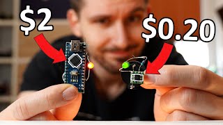
In this project I will try to remake an AliExpress PCB. It is a very handy voltage converter that can take a varying battery voltage and convert it into 3.3V or 5V while only requiring very little current (25uA) on the input. Sounds awesome, but the board is way too huge. That is why I try to push the size limits in this video to the minimum. Will I succeed?? Let's find out!
Websites that were shown/used during the video:
www.ti.com/lit/ds/symlink/tps...
Thanks to the Würth Elektronik for supporting this video.
0:00 This Board is TOO BIG!
1:31 Intro
2:15 What Components to use?
5:02 Making DIY Version 1
7:08 Testing Version 1
8:35 AliExpress Board Comparison
9:10 Making/Testing Version 2
9:58 Making/Testing Version 3 (Tiny)
11:04 Verdict - Věda a technologie


Important! My own designs here were not EMC tested. I will explore that topic in a future video ;-) There we will see whether my boards follow guidelines and how we can possibly change the design to make that happen. Also we will test the Ali Board as well concerning EMC. That will be fun. I hope you are looking forward to that ;-)
Also if you are interested in Würth Elektronik products/services then you can contact them directly if you are a company or business: www.we-online.com/en/products/components/ordering-form
But if you are a without a company then you can contact their distributors about their products: www.we-online.com/en/support/network/distribution
Thanks for useful board!
Please make a video on rda5991ic it is a multipurpose ic with features like it integrates 802.11b/g/n MAC, PHY, 2.4Ghz radio, PowerAmplifier and
antenna switch into one chip and is optimized for mobile applications. WLAN, Bluetooth and FM can work simultaneously and independently, with low power consumption levels target to battery powered devices. I have one lying around but couln't find its pinout or schematic. Please help.
Looking forward to it. You're such an inspiration.
If there's time, it would be fun to bring in a Pololu converter board as well - they're a lot more expensive than Ali Express fare but are nominally backed by a name brand and are the smallest off the shelf converter boards I'm aware of (albeit still a bit bigger than your design)
Yeah, whenever I've experimented with these kinds of regulators, one of my first tests is doing a conducted emissions test. And doing that test at multiple current draws. Without an input filter (which none of the reference schematics ever have), I wouldn't be the least bit surprised if all the designs fail.
Another idea to get it even smaller: This is a non-isolating converter, so you don't need a GND pin at output. That enables you to just put all the contacts on one edge. GND in the center, and capacitors on the sides in between. I bet you can make it smaller if you place more components on the backside too, but for manufacturing all components on the same side are prefered.
Thanks for the feedback. I guess there are many way to go even smaller. But still, I was pretty happy with the outcome.
pololu does it this way, with 3 pins, like it
Why bother with PCB? 3D assembly, drag a copper thin foil for heat dissipation and blob everything in resin...
Here's trick to minimize components: but a high tech factory that will allow you to make transistors the size of few atoms
Great idea! Making it pin-compatible with a 7805 for example.
Also, if you need to solder-blob the voltage, why not just use a different resistor (and loose one).
Perhaps you can even get everything on a single side (no hand-soldering required)
Experienced engineer here... Looking at your PCB design i noticed that you make so called via-stitching equally spaced, which is a bad habit. Especially in fast switching circuits. That's because those places often become nodes of the high frequency standing waves, which in result amplifies the noise, energy loses, and destroys the electromagnetic compatibility of your circuit.
This is quite unintuitive, but randomly placing vias (which for an untrained eye may seem unprofessional and ugly) in fact makes your circuit better!
Exactly the same for mechanical noise - for example when making strengthening ribs
@@martinfisker7438 Is that because of resonance?
Thanks for your comment! I always want to make it look neat. Can you name more pitfalls? ❤
top tip, thanks for sharing!
While browsing TI's product page for the TPS63020 I came across the TPS631000, which TI itself describes as 'Upgraded product with 8-uA IQ and smaller SOT package.'. It would be really cool to see you make a board design using this chip, especially since i couldn't find any boards using this IC online.
I can put it on my to do list :-)
@@greatscottlab Awesome! I look forward to it, thanks for the great vids
If you care about Iq you can go even below that. TPS63900 has only 75 nA, even though the current limit is a bit lower.
TPS63900 is brilliant, I used it in my low power system, it's incredibly versatile.
TPS639011 is a good and affordable option especially with the new technology… however, if you want better transient response with less passive components, tps63807 is a recommendation. - a TI employee
This was very timely for me. I would love to see the lipo charging ic built into a tiny board like this - that’s something I need for lots of small projects
That is the cutest reflow plate I've ever seen!
Thanks GREAT Scott. I like this video, just like all the others you have made. You and Captain Dissolution are 2 of my favourite creators
Always a pleasure to see your projects.
I'm excited for that EMC testing video. Great video, Scott!
Oh this is definitely just getting started. Can't wait to see the followup.
I really like these old school circuit design videos!
I really enjoyed this video. Showing the progression as you removed components, especially capacitors. Very informative.
Glad you enjoyed it
I would love to see more miniaturization videos! This was great.
Truly an inspiration as an aspiring engineer. Excited for the next video!
Really nice!
Awesome circuit for the really low power stuff, where the DC/DC-converters own current consumption becomes a significant part of total power draw.
I love videos that show design and iteration! Thanks. I would be good to know the design lifecycle from starting design to the EMC tested final product. An evaluation on component cost is probably a factor that influenced the size.
Brilliant, dude! Fantastic work!!! 😃
Looking forward to the EMC tests!
Stay safe there with your family! 🖖😊
Very timely, I am searching for compact supplies like this. Looking forward to the EMC chapter!
I love your videos. There explained so well and I always learn, some videos I bookmark for future reference in case I need them. Thank you!
Nice little chip. I have considered using it for backup power for some home-grown smart home devices but ultimately didn't go through. I missed one thing from the video though, that can make or break a power supply and that is capacitor derating. Class II ceramic capacitors are pretty nasty and change their capacitance if they are DC biased and me not taking that into account actually cost me weeks of troubleshooting because of unstable power caused by the lack of capacitance at the input. TI has a pretty nice online design tool that helps you find derated values and most capacitor manufacturers have a public database.
P.S. Thanks for reminding me about this IC, I have a project where it should serve me perfectly
(Edit: corrected grammar)
Thanks for the feedback. I will look into that.
I believe the usual rule of thumb is to order MLCC caps with at least twice the voltage rating you need.
@@Jefferson-ly5qe I heard it and while it is a good idea to oversize a bit, every capacitor has its own unique voltage-capacitance curve. I have recently looked at two 10uF 50V caps, one was 1206, the other 1210. The latter one had half of its rated capacitance at 25V, the other was already under 1uF. And that's not even accounted for changes because of temperature. And it made a huge difference
Pcb designing for switching converter is actually pretty intense and interesting
The way you place your current loops become very important
I recently did first attempt at pcb designing and have it fabricated
( Not good but usable)
Useing kicad
I highly recommend Phil's lab vids if anyone wants to know more about it
Thanks for the feedback. And yes, Phils videos are definitely more in detail and super useful.
Most awesome...and the fact it can put out fairly stablish 5vdc at 2A (might need a wee bit more output filtration)...it could be used in a DIY UPS (with a charging IC) to build a pretty decent battery backup/UPS for a SBC...
Very cool on the "miniaturization" of the board! Great job!
Keep em coming!!!!
Very neat. Receiving new boards is so exciting. I use tiny 7805 pin compatible switching regulator boards in my designs at 1A. They're still smaller than yours, but the 2A is impressive.
Wow! That’s amazing! Also, those inductors are incredible for their size!
I’ve been working on a PCB which needs to put out 5V with as much current as possible, as small as possible, which runs on a single 18650. I ended up landing on a TI chip as well that’s just amazingly small for the power it can handle.
It’s a fun challenge!
Thanks for the feedback. Sounds interesting on your side as well.
that sounds like a good thing for raspberry pis!
Great video as always. Looking forward to the EMC video!
I am designing something that does use this IC, I have never designed anything of the kind before and this video was indirectly a great help
ty man
You are welcome :-)
This is such a great video, because I am currently in need of a tiny PCB with six different power outputs
Great job showcasing this. Thank you
I watch all your videos and learn something new everytime thanks 🙏.. love from india
That giant wurth elektronik case of parts looks amazing.
I like this style of video, keep it up!
Very neat, looking forward to the follow-up video!
Thanks! 👍
Excited for the emc video!
Awesome video idea! Very interesting! Keep them coming😊
Really nice work and i would like to see more like it also great utilization of the sponsor
Excellent work! I try to use thinner PCBs for smaller projects. 1.6mm is fine for large boards, but small PCBs look "nicer" when they are thinner 🙂
Brilliant and so, so useful. Thank you again.
The only pcb I've seen that makes that hotplate look big!
I find your video very informative as I'm currently designing a boost converter based on the Texas Instruments LM5158. On a two layer board 0.8mm might offer better emc with the same cost as the 1.6mm. looking forward to your next video on this.
Fantastic, this could be the kernel for a while family of useful parts added on because it's so small. Usb-c recharging, very portrait and very square form factors for pen/cell or low profile spaces, single sided and double sided for a flat surface or smaller size, a prototype board with lots of breakouts and led indicators... 😁
Man I really started missing this type of videos of yours, thanks for returning to theme 💘
No problem. My main topics do vary from time to time. Always electronics though ;-)
@@greatscottlab glad to know 😂
Every day you upload a video is a good day. Thanks for your work! Keep it up!
Thanks, will do!
Your "solderable by hand" threshold clearly is something else :o
This channel is making me want to get back into the electronics hobby.
Been working on a 3.3v reg for a work project to power a small SoC, which has been an interesting dive into TIs catalog. If you ever want an interesting design project, something similar is extremely interesting.
Thanks a lot. I’ll design another pcb like yours but includes tp4056 with bms components to have em all in a single board!
Cute, BUT!
Check out the TI's "power modules", which have the inductor integrated. They are spectacular! Tiny, very efficient and absolutely great EMC-wise, as the noisiest switched node doesn't even leave the module.
For your application, TPSM83100 looks like a great solution and could easily get you to 1/2 size of your final board.
Also, 8uA Iq for the mentioned chip ;)
Wow, those are really good to know about. Thanks for posting about it.
I love this. Great job!
Well done. Nice work. I hope that you sell a million of them!
The vias and the ground plane also serve as thermal management like a heatsink. I have been afraid to make some boards smaller that it may raise the operating temperature of the components and shorten their life.
love ur work 🥰
Multiple different size (and or type) capacitors are better at filtering noise than just one large one. Inductance might also play a role in choosing multiple capacitors.
In what application you would want to do that? And when do you know when you need multiple small ones? And how to determine their values?
@@cryptophoenix3031 I was reacting to Scott saying he could use one instead of three capacitors.
Trying to find a good combo of types & sizes for filtering noise is quite difficult - as it is very dependent on the frequency response characteristics of the types of capacitor you use. Most manufacturers won’t even give you accurate ESR/ESL values to model with so you have to measure them yourself.
A single large capacitor (especially an MLCC) probably will also have detrimental impact on the frequency response of the controller. I wonder what the transient response is like for the boards.
Good work again 🎉🎉
Great job, i am very courius about their EMC tests, hope it comes out soon!
I do not want to ruin your day; but it might take a little while.....
@@greatscottlab Well, i will almost certainly look forward onto the next video topic too, keep the good work man, i wish i had started an analog electronics channel too
very impressive work as always!
Thank you! Cheers!
I am amazed anyone can solder that tiny, i for sure cannot. Good video as always.
0805 is definitely possible. 0603 also. Tinier than that and it becomes a guess work. Maybe I should do a challenge video about this ;-)
@@greatscottlab I find 0402 to not be that difficult. 0201 takes some patience though. Haven't tried 01005 yet.
Not difficult when using good solder paste (Sn/Pb) and hot air. Very difficult if one insists on lead free solder and an iron.
@@greatscottlab YES! I would love to see that. I can't even do 0805, let alone smaller th an 0603
Danke Scott für ein weiteres super Video. Beste Grüße aus Hannover (:
Danke fürs zuschauen :-)
Great video 👍
A few suggestions that could improve performance, and keed all components on one side.
Move all important text to bottom side.
Get rid of designators and component outlines.
Then you will have more space for decoupling capacitors.
Not all capacitors are created equal, especially not MLCC class 2. So you may want to look into the delta C as function of delta V. This depends on package size, dielectric and vendor.
If only area is important, the use one 1206 instead of two 0603, as you can find taller 1206, which is more volume for capacitance.
Perhaps a 1206 polymer tantalum.
Move input and outputs to the eges of the design, perhaps even castellated holes.
Share input and output ground.
Resistors could be 0402.
Tiny SMD boards are great. You’re minimizing trace distance, they’re very easy to stencil, and you can just drop it on a heated board to set the solder. It’s a win-win-win!
Really nice video!! I was wondering where do you order the manufacturing of your PCBs once you have a design to test. Keep going with this quality content 👏👏
Awesome work
Super cool project!
At last something exceptional.
Super useful video Thanks!
ECM tests would be nice. From time to time I visit EMC lab, it looks crazy :D good job as always!
Good engineering!
Great video overall and a good option for many applications. Would love to have seen you go down in resistor size to 0402 since the ones you used are pretty bulky. Also, would recommend using flux when hand soldering as it would result in much better solder joints.
0402 resistors are so fun to use... soooo tiny! but certainly helps shrink stuff down!
I didn’t get a good look at your layout, but adding some additional ground layers in the middle of your board can help with reducing output ripple. It is also helpful to “isolate” the feedback node by ensuring the feedback trace is thin and doesn’t go anywhere near the switching node. Same thing with the ground reference for the feedback divider, have it be a trace that goes straight to the return of the chip and ensure the power paths are “separate” if that makes sense. Great video! Thanks for sharing!
Yep ... and placing bulk cap on the bottom layer of a thick 1.6mm two layer pcb will render them almost useless for high f noise surpression 😢. For driving Leds it will work, but ur emc engineer will jump out of the next window 😂. Pro Tip READ THE FRICKING DATASHEET ...
Nice project, but in the end one should approach it as an engineer would and list all of the requirements of the circuit and see if it is feasible at all and then trade (space, components, count...) to achieve the goal. Strictly going to "small" (as shown) compromised noise and current. Then of course need to consider the operating temperature range and likely other issues (supply side noise, vibration, etc). This is a great channel!
Great design, but you should consider the max and min ambient temperature to check efficiency and ripple 😊
Thanks i love electronics since i was a kid i dissasebly my toys and radios and stuff now is my hobby im a welder iron worker but i love electronics .i used that board to mod my gameboy advance with a lipo battery
I think that you should try adding back some of the smaller output capacitors. That should limit the output noise (voltage swing) at higher frequencies. Also I have a question on your measurements - have you enabled a 20MHz BW limit in the scope? This is the "industry standard" when measuring power supply noise.
Impressive how such a small board can deliver this much current. Technology is improving more and more :-)
Yeah pretty awesome stuff :-) I bet we could go even smaller though with some converters that switch with GaN FETs. But that is a topic for another video ;-)
Hi you have to check PFM based DC converters. TI and Toradex have pretty cool ones. They can operate as low as 1 uA output power.
When I have developed an ultra low power circuit / controller ( sleep current 3 uA / run current 200 uA ) this was the solution.
Quiesen current where around 500 nA of the DC/DC
your a legend, iv been watching you from when i was 5
Oh boy. Very early. Crazy to believe that. Awesome for you to stick around and learn more :-)
Yo so how old r u right now?
Looking forward for further explain EMC emmition.
Great video. Could I ask where you got that reflow plate from? Looks very handy
Speaking of really small electronics, I've been looking for an excuse to use the Renasas DA14531. The SOC somehow includes a buck/boost and ble radio in a 1.7x2.05mm package. So if you make miniaturizing into a series it might be one to check out.
ST had or has some SOCs with built in switch drive signals too. Last one I saw even had two.
This is brilliant! Could you share details of that small hot plate pls? It would be so useful to me right now. Thanks in advance.
As always nice video!
Thank you :-)
In my opinion the Vias job here is to act as a heatsink and keep the IC as the ambient temperature because the FR4 material is not good when it comes to heat transferring.
Overall good video as always, keep up the good work
Yay, EMC topic!
Maybe some shielding to lower the noise? Even just a secondary ground plane over the top may help. You could probably test it with foil until you find a solution before making something rugged, but it's a thought.
Also, using more of the back of the board, especially to try to isolate the inductors.
Shielding is very unlikely the issue, we’re not talking about coupled noise here (it’s power source, it’s a very low impedance node). The noise is probably resonance based, the caps and inductor having a particular noisy resonance at that frequency.
Wow, 25uA that's brilliant 😊
Awesome keep going!!!
Thank you! Will do!
Love the AliExpress series, keep going !
Great Video!
great job
For low power applications I would actually recommend LM3671. It is small (SOT-23), it only needs 3 external components, it is 16uA quiescent current. Pairs really well with a 0806 form factor power inductor from Murata.
Nice video. I know you said you wanted to use 0805 components, but since you were reflowing, 0402 resistors would save you some space
This video reminded me that in 2014 I bought an Accurite Temperature/Humidity monitor. I stuck a brand new Energizer battery in it. This device is still being used 10 years later with the original battery in it. The device is always on and always displays the temperature and humidity and cannot be turned off unless you remove the battery.
I think when we see overspecced components on aliexpress stuff like this it's mainly cost based. Not that cost can't be lower with the right components, but a lot of the time I think what happens is they say "oh we have a bunch of on hand, lets use that" or "Our other factory makes this part so we can get a better rate on it".
It can surely be made even smaller - the in/out pads are huge in the final design and they take space on both sides. Change them to the single-sided smaller soldering spots. Same about the voltage selection jumper: you can reduce number its pins from 3 to 2 by making it short a resistor in series (or not short for 5V). Or you can eliminate it completely by just soldering different resistors depending on desired board output voltage. And you can put more capacitors on the back side to bring the noise back to acceptable level.
Whoa! Would you talk about those organizers you have for you 0805 parts? Everybody goes crazy trying to figure out how to organize and those look amazing.
Truly it's crazy tiny 👍🏻
Thanks :-) I bet you could squeeze it all a bit tighter together. But all in all very happy with the result.
Nice looking PCB
Thanks 👍
Nice work.
Thank you! Cheers!
Thanks, very interesting.
WOW 😲 Nice work! What i observed though and will be great to know, was the mini ocb solder reflow unit. That will be ideal for my current design. Could you please let me know a link? Very much appreciated.
Peter
Very cool!!
Looks great, and a fun project! -- Wondering if there's a way of dealing with the vDroop?