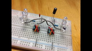
Traffic light LED circuit using 2 555 Timer IC on a breadboard

Vložit
- čas přidán 29. 01. 2023
- Build a Traffic light with LED's, (x2) 555 Timer IC and all on a breadboard.
No need for transistors in this circuit.
Components:
2-555 Timer IC
2-100uf Capacitor
1-100k Resistor
1-47k Resistor
3-330 Ohms Resistor
Breadboard
Connecting Wires or Jumper Wires
9V Battery
You can find the circuit diagram here.. www.roleneskosan.co.za/traffi...


Thanks for demonstration, it's easy to follow with the narration. well done
I really liked this circuit because it's very simple, and it doesn't use the 4017 IC. Congratulations for your excellent project and for the narration too. 😊🇧🇷
Hello I am making this for one of my project which will be better cd4017 one or with 2 555 timer .
I will make this on pcb
With your great instructions this was a fun project to build. Thanks!
What an excellent explanation for the implementation
Thanks for the Circuit and good presentation.
Thanks for this knowledge❤
Just finished it and tested ok.
Good work with the light traffic
I like this circuit, can you adjust the time that the colours change by using capacitors of a different value?
Very easy thanks.
i take back what i said i had a bad timer it works perfect i followed you
Some may have missed this , but the Pos Red and Yellow are on the same line of the BB so a single line to + buss get both. The - end Cathode is on two separate lines. If you have one light not flashing this may be your problem. also check the wire connections from the diodes and their polarity. Long leads are +. A coin 3volt battery is a good way to verify that LED is good and give correct polarity, Do not use a 3.7 lit it will fry your diode . A schematic would be good but trouble shooting is part of electronics.
Can you explain it more for me?
And I want to know the mechanism of the circuit to light LEDs
How we can set timings of each led seperatley
You should add a pedestrian button! Would be cool to see
Eu gostei muito deste circuito por ele ser bem simples, e não usar o CI 4017. Parabéns pelo seu excelente projeto e pela narração também.😊👍🇧🇷
how to make the led still on?
Waw, You outdid yourself today,. Thanks very much.
Does it matter what volt you use for the capacitors? Looks fun I'm going to try building it right now
Thank you sir
Thanks 😊👍
It would be better if you could explain the internal circuit diagram.
I tried it the connections are right but it ain't working what should I do?
What could be the reason
useful ❤️
220uF/16V gagana Kaya ?
The link to the circuit diagram is not working
Do you have a diagram ?
For me only green and red led are glowing. How can I sort the problem? I tried a different resistor but it didnt work as well
My red wouldn't light. I found a jumper shorting it
I had the same problem with the red , short in breadboard
A força da maré
Is this project is available
Sir Can you please tell about it working principle and application
Can you tell how to increase or decrease every led on time
Change capacitors and resistors simpleton...
The sequence in the UK is Red, Red & Yellow, Green, Yellow, Red.
I imagine it’s complex to do.
Hi Richard Ashton, in South Africa the above sequence is most common.
Can I get the circuit diagram of this project please.
Did you find the circuit diagram of this circuit if you did can you please share it i have a PBL tomorrow I've been trying to make the circuit on proteus but isn't working
Pwde po BA Yan hookup wire LNG
Nice work but can you please 🙏 explain to me how the time interval are done among the LED to switch on & off
Hi @kpieceemmry3387 Thank you, we know that the capacitors in an LED circuit causes the LED to flash at a certain rate but in this case we also have two 555 Timer IC, which is in astable mode. The 555 timer generates a continuous output in the form of square wave via pin 3 which turns the LED on and off. The time interval between the LEDs is decided by the resistor-capacitor network.
@@roleneskosan_electronics sounded a little bit complex tho but thanks 🙏
@@roleneskosan_electronics bro one doubt bro
@@kpieceemmry3387 Lol she didn't even talk about the charging and discharging time constants of the capacitors which basically controls the timing. You probably need to do some study on that to understand it properly
Should Always passing the Yellow Warning That's the Right Sequence
I followed your instructions, but only the green and red lights are on. yellow is not on
Maybe ur led’s polarities are wrong?
Same issue
The first sequence after connecting the battery works correctly but after that the yellow is skipped every time.
Please send circuit diagram
Good
Yellow led isn't working
Schematic ?
No, it is so simple you could not understand it !!!
@@peatmoss4415 A schematic would have saved 13 minutes and 10 seconds of my life. A4 second snapshot of schematic is more useful and informative than the rest of the video.
Cool tutorial. And would be perfect if you explain each step, each component selection, why such component, what is each leg of 555 mean and why you connect them in that order.
Hi @romy4romy. Thanks noted and appreciate the positive feedback, I will do so.
Read the data sheet moron !!
Disculpe le falta el diagrama electrónico está bien gracias
My yellow light didn't glow....also green glow for 20 sec , and red for 8 sec
Built it exactly how your video shows it and only red and yellow lights are lit. Green does not come on and they do not sequence they just stay lit
Hi J. W. Defeo, try replacing your 330 ohm resistor which is connected to pin 7 of the second 555 Timer IC with a 470 ohm resistor.
@@roleneskosan_electronics I did, no change still can't get it to sequence or have green light come on
Same issue
Is your problem solved now?
Can you please draw that circuit diagram
Hi @user-cb2ve4jh8x, www.roleneskosan.co.za/traffic-light-led-circuit-using-2-555-timer-ic/
@@roleneskosan_electronics the negative terminal of the yellow LED is connected to pin 7 of timer 1 on circuit diagram and I think was suppose to be connected to pin 7 of timer 2
Unfortunately what you presented on the video and the schematic are complete different, even the components you listed on the website are not completely in the schematics
4 cekent off 1 cekent on blink ho banake dikhao aysa sarkit banao mord he to banao
😊😊
It is not working like traffic light instead it is like a random leds lighting up
Somtimes humans disapite me, like when i read this comment.
@Apex gamer You need to change your name to Dumbshit gamer. Watch the video over and over again in slow motion until you get it right moron....
Budget plz??
Lessthen 500pkr
4 secent me 1taime blink ho 1 cekent aysa sarkit bana paoge dam he to dikhao
Please drop a diagram 😊
Hi Austinwywm5012, you will find the circuit diagram here... www.roleneskosan.co.za/traffic-light-led-circuit-using-2-555-timer-ic/
I can't access to the link and please please please i need the circuit diagram for proteus @@roleneskosan_electronics
hi my green light doesn't turn on...😭😭
Polarities are different for green...re check it
My green and yellow light blink together and after some time red can anyone help me
dude after red it jump to green it has to be yellow first than green learn it
It is just light red led up, others are not
Hi, are your polarities correct?
@@roleneskosan_electronics yes
So what happens if you switch around the LEDS that aren't working, and if that does not work try replacing your 330 ohm resistor which is connected to pin 7 of the second 555 Timer IC with a 470 ohm resistor.
Yellow one in lighting up now, but the red one is still turned on
If there is anyway I can contact u
????
No schematic!! WTF???
Fake video
Maybe anyone knows why mine goes G>Y>G>R>G>Y>R>G>Y>R......