I made a SUPER FAST Line Follower Robot Using PID!

Vložit
- čas přidán 1. 06. 2024
- I'll show you how to make a line follower robot using a PID controller on arduino!
JLCPCB 1-8 Layer PCB at $2. PCBA from $0 (Free Setup, Free Stencil)
Sign Up to Get $54 New User Coupons at:jlcpcb.com/IYB
Get the motors and electronics from: www.dfrobot.com/product-827.html
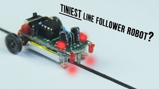
Making Line follower robot is one of the best way to get started with robotics and arduino. In this video, we'll be learning how to use the PID algorithm to make a line follower robot FAST. Using arduino, motor drivers and chassis, we'll put together a simple line follower robot using two IR sensors. Then using an IR sensor array, will make PID controlled version of the line follower. PID control stands for Proportional Integral Derivative where each constant affects the way the bot behaves. This video explains why we need feedback control and how PID controller is used.
Download code: github.com/theTechnowright/PI...
More details:
www.instructables.com/Make-a-...
Reference project(And BT App): www.hackster.io/anova9347/lin...
Chapters:
00:00 Intro
01:07 The Simple Version
02:39 Designing the bot
04:50 What is PID?
07:12 3D Printing
07:44 Track Design
08:12 Speed Test
Music from Uppbeat (free for Creators!):
uppbeat.io/t/mojo/rumble
License code: SA1IYLHH08X14CBM
Music from Uppbeat (free for Creators!):
uppbeat.io/t/all-good-folks/t...
License code: WX75GUM5SZLV79WJ - Věda a technologie


I'm not sure why this was in my notifications, but this was actually made really well
Same for me, this actually earns a subscribe
What an evolution from the Technowright! Love your videos, I've been watching them for years!
This is really cool. I have been researching PID for a bit now and this came up in my notifications and I'm glad it did. Great video and good distribution of humor and information. Thanks for showing the progress and the mistakes you made, mistakes are often much more valuable than the result. Thanks!
It is called 'Bang Bang' from the first days of radio control in which I played a part, trying to fly aircraft. there were three positions ; neutral, or BANG full right, or BANG full left ( and they did make a bang noise sometimes, using rubber escapement motors) - no proportional in-betweens
Ah Yes! Quality Content❤
Finally an explanation of derivative and integral error correction that makes sense.
Also, nice video overall!!!
It is unbelievable how bad teachers can explain this topic right 😂
Was thinking the same thing, if we had good and practical example while we were being taught, we would have loved it and understand so much better
Nice! Great style, and very educational.
Its maybe the fastest line following robot I've ever seen
Great work❤
love this video , so much fun
Excellent video!! Hopefully we get em more often though.
Damn! This was awesome!
Very cool , also love your apartment.
You are superhero ❤❤❤
Thanks from Egypt
Awesome vid! ❤🔥
Amazing job and expalination.
Great video!
First of all, awesome video, great explanation and demonstration of everything, i just added to my favorites! I just wanted to point out that you might've made a heavy load with that cool looking racing car model on top... and the tires/wheel you've chose does not have a good grip, its better to have something more soft to have better adhesion... another thing to consider is having bigger dc motors, those are very weak, specially with that load on top of it... please remember to take everything that ive said with a grain of salt because im not a professional at all... but i was wondering about that while i watch it run...
So nice innovation. Hats off🎉🤝👏
Good job bro❤❤
Damnn!! Amazing video Shyam, and awesome work. Loved it!!
Superb Shyam..keep rocking 👏👏👏
Best video i ever saw in youtube.. Good explaination bro
Awesome project, and thanks for your contribution
love it!
thank you!
subscribed! Nice video
3:26 MOST HELPFUL TY CUS IT HELPED ME TO MAKE A PROJECT REPRESENTING MY SCHOOL !
Finally he remembered that he also had a CZcams channel. ❤❤
thanks for sharing, would you make a video and tell us the PID tuning detials?
Superb Shyam. Very well presented. Engaging and entertaining… All the best
Thank you!
@@shyam-ravihi cam you share how to use the code? I mean to install that somewherw? First time
Hello sir!Nice video! can you please specify what sensor you used? and does it have a digital input or analog?
really nice, what was your base speed for the motors (to be specific what was your pulse width for the PWM)
Have you tried doing it with all analog circuits, except maybe for an esp32 to let you set the tuning values remotely?
love from pakistan. A good quality engineering video at last 👌
Awesome 🎉😊
Proud of you my son.... Hope to see you on another level....❤
Thanks a lot!
Another addition you can do to increase speed is speedup on straight sections and then slow down to normal or break on turn can significsntly boost speed
The PID algorithm does that automatically
Could you fit a kalmar filter on the arduino to underdampen the steering?
Totally worth it
Great video, thanks for sharing it. Although I do have one question, how were you able to determine the error value accurately with only 5 IR sensors!?, I've been trying to do the same thing but couldn't see it happening with only 5 sensors.
Please reply if possible
The IR sensors give an analog value rather than a digital one. So that adds to the precision in measuring the error.
Superb
very nice video and presentation. You are very well articulated and a pleasure to watch.
I am doing a project similar to the simple version that you show and apperantly I do everything correct but when a switch on the gears are not working.
After watching your video I guess that the battery I am using is the problem. What kind of battery should I use?
Very nice video shyam. Keep on rocking
Thanks!
Awesome!
Hi ! Do you think it is possible to implement an A* algorithm in a line following robot?
Hi ! which app did you use on the phone for controlling the PID ??
bro what are the components that you used separately on the pcb, and which app did you use to control the pid, can you please mention.
Have you tried your line following robot with dead end map and does it follow the line with a mixture map(white line with black bavkground and black line with white background)?
What IR sensor are you using? please tell me specific name...
Nice
Hi im quite new to arduino but im just wondering how you got the arduino powered without plugging it in anywhere? I mean looking at 1:57 there doesn't look to be any cable from the battery to the USB or barrel plug. how is it working?
Hello bro, first of all, let me congratulate you on the video. I'm having doubts about this line sensor. I have one just like yours, however, the sensor values always remain the same regardless of the surface it detects, whether it reflects a black or white surface, for example. I'm simply reading the sensors from the analog inputs, I'm not sure if I need to do something else?
Great project 👏🏻👏🏻
hello, can you do it with backward mode or can you guide me code with motor backward ? Thank you so much
Please provide a roadmap on how we can make one of these
What to learn first?
What is your kp and kd value that you're use?
bro's smart as hell
I have no idea about any of this, but I kept thinking, why not use a fast linear interpolation value to smooth out between all the hard value changes. Seems like that might act like a dampener between values and really smooth things out. Besides, I like lerp functions in all of my game dev programming. It just works great for so many situations.
And how you do that?I jus wanna learn abt it
@@adrianfernandes2004 Linear interpolation or LERP is taking a value and then cutting it up into a smaller part, then cutting that part into another smaller part. In programming you can do this to crate a smooth transition from one value to another that is not instantaneous. Lots of info available online, just search for "How to lerp function).
@@_cul8r_ dude thanks for explaining I kinda get it
bro Funtastic
Gold 💛
Bro i want the list of foot prints that you used for pcb design .
How necessary was the integral constant? Was it relatively small?
Would a larger integral constant yield a better response for an error biased towards one side? Such as one wheel having (consistently) more grip than the other side?
In the case of one wheel having different properties (such as better traction), you would have separate PID values for each wheel.
Super video
At intersection point , from 3 lines which line the robot will be choose ?? How robot decided about it ?? 🤔. Is the robot will be choose a line randomly every time when it reaching at that intersection point or you programmed robot to choose a specific line from 3 lines or any other idea you taught the robot 🤔 ??
VERY COOL, great work. But uhh, do you have the Code for the smart glasses
Hi friend. Great video. What’s at J1?
i want to know your parameter Kp,Kd,Ki ,multiP,I,D is always 1 ?
what software is used to set the PID value?
My brother what sensor are you using TT please tell me
Dang, your accent is so good
I agree
Is this follows LSRB algo. As well ?
How about using a QTR sensor?
Me and my friends were able to make a similar fast PID based line follower, during the build we realised that the gap between the IRs was also a deal breaker (QTR being compact, solves this issue) .
Also can you upgrade this to a maze solver next please, would be interesting to see that!
Good video!
Thanks for the suggestion, I did consider a qtr sensor, however due to availability issues I went this one. Maze solver would be an interesting project!
A very good video. Which transistor to use?
Which transistor are you referring to?
how can I use qtr 8rc sensor with this code?
Can you tell me the list of items you used please asap
Bro explained PID the best way possible!!
fuck
Maybe u can integrate ann (artificial neural network) to it, so it's can learn the track, to make it some kind of intelligence enough to run even faster.
Wow! Fantastic👏👏👏
How about front wheel drive?
hello
how to oder the pcb
please guid me
Bro can we use printer motor?
Nice project! What PCB design software did you use?
Easyeda
Can you please also share the 3D design
Nice! But we would all appreceate it if you would include some of the details in the coding as well
You mahe great videos. Have you got a new channel or have you just stopped? Updated ones would be great
I am starting doing projects with Arduino and I am interested to start doing the simple version you show in this video. What are those components where you put the photoresistors? Sorry for asking but I am not familiar yet with electronics and Arduino. By the way really cool video dude I enjoy it!
Think he used IR detectors not photo resistors.
Thank you.
I have see that I will need to do it with phototransistors, are they similar to the IR detectors? Or at least if I buy this IR detectors to practice will be similar?@@aakashjana6225
do you have to use an encoder?
It cant take acute angles right? Im working on LFR from 2 years.
Im using qtrx 16A line sensor with toshiba tb6612fng motor driver and teensy board, my lfr top speed is 6-7m/sec.
Do you have any idea to crack acute angles?
5:30 your app looks similar to "Bot reboot's" pid controller app, did you made this app or using his app for pid tune?
Yes, the PID alone isnt sufficient for acute anglee. So, I coded it so that once it leaves the line it checks the previous error and turns to that side till its back on the line. This worked well on the acute angles.
@@shyam-ravi you mean, in this code it can take acute angles well?
Yes, it handles the acute angles quite well. As you can see in the video.
@@pocopoco3468
Which motors are you using
Rpm
Voltage
@@shubham9672 N20 gear motor, 1000RPM 12v
How to purchase this project
May i ask the link of the parts?
Please teach about your program
IS THERE A CALIBARATION AND RUN BUTTON? or just turn on power and run
First 10s calibration and run. There is no button for it
@@shyam-ravi how can i contact you bro
@@shyam-ravi bro i followed your exact tutorial, nothing happens, even bluetooth of esp32 does not show up on phone
can it be used for maze like pathways ??
please reply asap
You can, but that would require separate algorithm or sensors
Great work. Just one question, Can we use PID in Arduino UNO?
Yes, you can
Yes
It's just a equation which can be written in lines of code
where is the app download link
I dare you to make a reaction wheel based vehicle following the same path, faster ;p
"All that glitters is not fast"
- Sun Tzu, The Art of War
it's hardly "fast", but good job on the presentation and project! (see videos from Japan's linefollowers or maze solvers, or from Europe's Robochallenge linefollowers...)
Bro please make a explained video on coding part