Video není dostupné.
Omlouváme se.
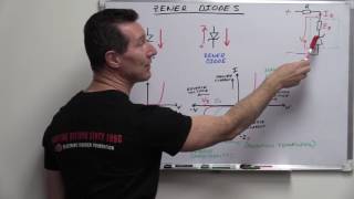
Zener diodes are not what you think

Vložit
- čas přidán 27. 07. 2023
- Correcting some misconceptions about a Zener diode as a perfect voltage limiter, regulator or reference. Many beginners believe, that its reverse voltage drop (Zener voltage) is absolutely stable. In reality, the Zener voltage can vary depending on the reverse current and the temperature. Measuring the real life current-voltage characteristics of some Zener diodes.
The next part:
• Simple DIY curve trace...
Please support my channel on Patreon:
/ diodegonewild
Instagram:
/ savage_danyk


The difference in the soft/sharpness of the zener knee between diodes above 5.1v or so and below is due to different breakdown characteristics if I recall. Below a certain voltage category, zeners rely on zener breakdown mode, and zeners rated above a certain voltage breakdown in avalanche mode. Worth looking into it's quite interesting. Hope I remembered right
Yes this is correct, the academic term should actually be "Zener diode" for diodes with a breakdown voltage below 5v and above 5v breakdown voltage they should academically be called "avalanche diodes" however nobody follows this convention so they all get bunched up and called simply Zener diodes no matter which is the underlying effect they rely on. (Wikipedia has articles on both the "Zener effect" & "Avalanche effect" breakdown phenomenon but I can't link them directly here.
@@perhansson6718 yes!
Also because of this there is a change in temperature coefficient around 5V. Below 5V the temperature coefficient is negative and above 5V it's positive. Theoretically you could get a 5V "Zener diode" with zero temperature coefficient but it doesn't appear to be a real thing. I used to use 6.4V "Reference Diodes" which were a 5.8V Zener diode in series with a forward biased silicon diode in the same package. The positive temperature coefficient of the Zener cancelled the negative temperature coefficient of the silicon diode giving a very low combined value, only valid at a specified current (1mA). I believe that they also selected the forward diode to match the Zener voltage and give an accurate regulation voltage of 1%.
Just how correct do you think you are ?
;)
.
My tutor recommended using (IIRC) a 6.2V zener diode if you were going to use one as a reference voltage, as they apparently had the best overall characteristics. Mind, this was over 35 years ago…
Also, use a constant current source and decoupling capacitor.
But the main question remains: Which of those diodes went wild?
Hmm?
Of course the hottest one. 😁
One in FULL BRIDGE RECTIFIER!!!
You're the IDEAL Diode in my books !....cheers.
Wie immer gut und informativ. Die beste Aussprache.
Watching the video "Zener diodes are not what you think" I've realized that Zener diodes are exactly what I think. But I love your videos anyway.
At 10:24 I think that the top (red) circuit might be better. The discharge current is limited to the leakage current of the Schottky diode which should be lower than the bias current of the TL431. The voltage drop of the diode doesn't really matter because as the capacitor charges towards 2.5V the charging current tends to zero and the voltage drop of the diode also tends to zero. So you could probably use a silicon diode and get even lower discharge current.
Thanks for the lesson on diodes, it was most interesting to see the difference between components from the same batch. The cat looks like it found a nice sunny spot. I hope you are not getting the high temperatures where you live. For us in southern Australia we have had unusually low temperatures.
Ďakujem za video, síce toto už dávno ovládam, ale rád sa pozriem na pekne vysvetlené video aj na tému, ktorú už poznám :)
As a noob to electronics i dont know how anything is supposed to work so i appreciate the knowledge you and other youtube eduacators share with the rest of us. I know a lot of youtubers think their audience are professional engineer experts by the way you talk to us it seems, but a lot of us arent, so are open to the correct way of knowledge. Infact im just waiting for someone to teach electronics with the correct way electrons flow, screw the old schematics i dont care, i dont want to learn the backwards way. But by the sounds of it we really dont even know how electricity flows (see veristasiums video), the fact theres even a debate about it tells me thers lots we dont even know about electricity, which makes even more exciting to get into, with an open mind. How do diodes even work? Yes they block current one way and not the other, but how? Thats facsinating on a atomic level.
Keep watching. I absolutely know what he's talking about just by watching their videos. And then reading, experimenting a lot now. It is a massive jump.
You'll be able to find lots of info on how diodes work on the web. The trick will be to find something that is at a level you'll understand. Some of it will be too simplistic and some will be far more complex than you'll want at this point. I'd start with a search phrase like _silicon junction diode_ or _PN junction diode_
Get used to conventional current flowing from positive to negative. It ain't gonna change any time soon.
Zener diode higher than 6.2 are actually avalanche diode not zener diode. The zener effect has negative temperature coefficient and the avalanche effect has positive thermal coefficient. A 6.2v zener diode has almost no thermal coefficient because it has both zener effect and avalanche effect and their thermal coefficients canceled out.
I was thinking you probably could bias the Zener diode with a small-ish current and use a power transistor with a high gain, or a MOSFET with a high sensitivity gate, to shunt the rest of the current.
But that's probably most of what's inside a TL431 anyway, so you may as well use the IC that's made for the job, if it does the job you want it to do .....
Bipolar transistors can be used quite successfully that way but MOSFETs are more of a problem. The reason is that the base-emitter voltage of a bipolar transistor is reasonably predictable. It does vary logarithmically with current, has a moderate temperature coefficient (about -2 mV/°C) and will vary a bit from one transistor to another of the same type, but all of that is often acceptable, depending on what you are doing. You can use about 0.7 volts as a rough guide. The threshold voltage variation from one device to another of the same type MOSFET tends to have a much larger spread and can be a few volts, depending on the device. If you are fairly new to electronics it can be a good learning experience to experiment with such circuits. You don't need expensive instruments.
The TL431 (which has been around since 1977) uses a bandgap voltage reference with a high-gain amplifier that can sink quite a bit of current at its output. It's a device worth getting to know because it can be used for things other than just a voltage reference.
Ahoy! Thanks! your video helped me understand zeners better as I have never known how to use them. I appreciate your effort and knowledge :)
Got a box of 12V and 24V 400mW zener diodes, and I use them mostly as regular diodes. They work well below zener voltage, so have been pressed into use as clamp diodes on relays, and also for capacitor dropper supplies, as having all 4 be a zener does mean I save on a diode if I want 12V out, just add a smoothing capacitor. I also used them, 4 in series, forward biased, exactly to clamp the voltage on a supercap, to replace the NiCd cells in a clock, using 2 supercaps, with parallel diode string, to replace the cell, as the forward voltage drop then was clamped to roughly 5V, and the supercaps only see 2V4 across them. Saved needing to change the cells, as they normally die from the slight trickle charge killing them, and run time is more than any power cut will be.
Inidentally, if you run the glass diodes at around 1A, they tend to emit light for a second or so, as the glass case melts, and the glass becomes conductive.
Very educational. Thanks 👌
The battery overdischarge protection on a makita LED light is quite complicated, it uses a tl431 wired to a transistor that shuts the reference down as well as the load. It is started with transistor/capacitor bootstrap circuit. It had 3 transistors and a reference if I remember correctly.
Those 18V Zeners look like ideal zeners with resistors.
6:42. Amazing graph, as always. Thank you for the fun and informative video.
Hi, nice video. I have 2 timers. One was in in socket and other one was on DIN rail. In both timers has zener diode short circuit. I replaced and nice works.
Thanks Dany, still loving your videos.
It's always nice to do a refresher.
köszönöm
Looking forward to the next episode! 🎉
Nice informative video. Keep 'em coming.🎉
i have always made sure that the amount of current used for regulation is always higher than the knee point. to keep it away from knee and into it's more stable operating area. As always read the data sheet before you put it into your design.
they should be used as part of a design and not the sole point of limiting the voltage.
If you can do that, it's great. There are lots of circuits where it would be nice to use a zener for bounding a signal where the rounded knee is a big problem. There is one series of zeners that I found that is much better suited for such applications (sorry, I don't recall which; I don't do this stuff anymore).
Operating around the knee can make a zener into a useful noise source with a pretty broad spectrum.
Looks like a zener diodes are wild 😂
*We need More Videos like this* 😍
After discovering the TL431, Zeners became obsolete for me.
Zener becomes useful for under 3V supplies which I've never used on any project requiring a voltage reference.
Whenever I could possibly use a zener, I almost never have the correct voltage and 431 it is. All of the guesswork with zeners isn't worth the trouble if you require any sort of accuracy or efficiency.
They are still convenient to use for a lot for applications that doesn't require an accurate voltage though - for their simplicity. Many applications is tolerant for variations of a few volts, but will still not handle huge voltage variations from an unregulated source.
One example I have used them a lot for is small flyback converters with multiple isolated outputs. For those, the feedback for voltage regulation can be put on one winding and the regulation will work for all of them. But this requires a small load on the non feedback windings to work. This can of course be done by putting a load resistor on the outputs.
But if the output voltage is not critical, a more efficient way is to put a zener diode one or a few volts above the nominal output voltage to keep voltage from rising too high during no load condition.
It can also be used on the primary side as a more efficient alternative to a snubber circuit - to "filter out" the small voltage spikes caused by leak inductance in the transformer.
tbh the design of the solar charger with the diode actually solves quite a few issues, as it will asymptoticly charge the capacitor with lower and lower current as it gets close to it's maximum voltage. also the 2.7V zener dropping by 0.3 when it's at 3V actually makes it safe again.
so it works pretty well if you do it naively, but mostly because of luck.
The Zener and avalanche breakdown mechanisms are not only dependent on the design current of the device. They are also very noisy. If you operate such a device on a very stable current source the voltage will fluctuate with a hell lot of excess noise compared to an equivalent metal film resistor operating at the same constant current.
Yep TL431 to replace zeners between 2.5 and 36V for much better reliability and accuracy, its a no contest. Everybody knows the zeners in an old telly or whatever will likely be dodgy.
Unfortunately TL431 can’t be used as a reliable overvoltage protection component, zeners and transzorbs have to be used because of their large current pulse capacity.
Where are the closed captions? I can't understand the video super well without them
Reverse bias transistor be connection makes a good low current zener diode for some applications
A reversed biased transistor can also act as a noise source biased with a high value resistor. It will need to be amplified either by another transistor or an op-amp stage.
As a perfectionist, this disappoints me so much
Beautiful explained 👍👍👍
twice i had built a indicator for battery charging which should light up when dc was present using schotky diodes, in the absence the supply the led had a faint glow from the battery, showing the leakage from schotky.
I have a Z-diode with 1.5V in the power supply kit. But the Zener effect is not used at all. The diode is not operated in the reverse voltage, but is a normal diode with the forward voltage of 1.5 volts. So there are two diodes connected in series in one housing. A red LED with a voltage of 1.6 volts could also have been used. The z-diodes are used in the circuit for the current source for the OP-amplifier.
A bit off topic but I wondered why CRT monitor flyback transformers have a few nF built-in capacitor but TV flybacks dont.
My only question, why did the rectifier get moved? It was fine where it was D:
In fact, you could just remove the sucker entirely in that second schematic! It does basically nothing except drop the solar panel down by ~.3v...
Also try LEDs as zeners, it's really good for a quick low power reference + provides visual cues to circuit operations!
Awesome DIY power supply, now I have to DIY one for me too. About the Zener, how to figure the load resistor ???
The most TL431s I found in a power supply was 5 of them! I don't remember exactly, but it wasn't something special, just the power supply of a laser printer or a PC (but not in the usual ATX format). But yeah, unless you're fine with the "stabilized" voltage varying ±20% a Zener diode is the wrong part (of course it can be a lot more accurate with additional circuitry, but that's usually not what you want to do). So for anyone tinkering: just ignore Zener diodes, unless you have a really good reason to use them.
I have TL/LM431s in almost any circuit that uses opamps. I've a bag of TO-92 packaged TL431s (not that I'd need those; I get more out of disassembled switch mode power supplies than I build into circuits 😆 ) and a bag of SOT-23 TL431 (which the Chinese managed to mislabel so they are actually TL432, where two pins are swapped; I still design my circuits with SOT-23 TL431, but solder in my "TL431" upside down 😅 ). The TL431 are very versatile (the 555 of references and regulators 😉 ). Just recently I built a relatively high input voltage linear regulator (higher than the usual LM78xx and LM317 can go). A TL431, a transistor and 3 resistors is all that's needed to go from over 60V to 10V (for very low currents obviously, as it's a linear regulator).
I suppose that usually the temperature of zenerdiode affects the zenervoltage. And bigger dissipation, bigger temperature, bigger change in zener voltage. I have tried to use series connected zeners to lower too high B+ voltage in tube amps and it is a bit difficult because the voltage drop usually gets bigger after startup. And the opposite behavior would be a more desirable option.
You could try a rectifier diode in series with the zener. There will be a 0.6v to 1v increase with this method though. Use a 1N4004 to 1N4007 400v to 1000v rectifier diodes.
Have a look at a datasheet for a family of zeners and the ap note _Zener Voltage Regulation with Temperature_ from Microsemi. The tempco of reverse voltage changes from negative to positive at around 5 volts where it is close to zero.
You likely have little choice but to use a more elaborate circuit for what you're trying to do.
Thanks!
Thank you for this @DiodeGoneWild 👍
I am a novice & a little confused so maybe you can help? I want to shunt the unregulated input AC voltage from an alternator before it is rectified by a Full Wave Bridge Rectifier that I will make using Schottky Diodes & a Capacitor to filter the wave so that I am able to use as low voltage SCHOTTKY Diodes that are needed to support a low power DC lighting & battery charging circuit of 7.5 to 8 volts at 500mh to 1.5Amp load - so minimum forward voltage drop is needed & protect both the rectifier circuit components & the load from the high voltage the Alternator can reach at speed.
My question is this. To shunt the AC input voltage do I need just 1x 7.5V ZENER Diode across the AC terminals or 2 x 7.5V Zener Diodes wired back to back & would a TVS DIODE be better for this? If so do I need 2 x TVS Diodes wired back to back across the AC voltage terminals? I would be grateful if you could advise - thanks!👍
Apparently, 5.6V zener diodes are the most stable because opposing temperature effects cancel each other at this voltage.
Great overview. These gotchas are what engineers know about. Ideal electrical knowledge is nice but not enough.
Nice 💚👍🇲🇦
Im currently building a bicycle hub dynamo circuit to charge usb devices, and to power up my lamp, which in I want to have a little delay before it dies after I stop riding. It is interesting that it generates about 1v per 1km/h, so I would have to make some overvoltage clamp protection because regulators have about 30some Volts max on input.
Low voltage zeners are just diodes in series polarized forward (2.8V = 4*0.7), that's why the curve is less steep/sharp than a higher voltage zever.
Many thanks
Thank you for your support! ;)
Can anyone recommend a PSU for powering a storage server with 25 SSDs (rated at 5v). Each SSD consumes about 4 to 5 watts of power on peak load. So 25 SSDs theoretically consume 100 to 125 watts under load. I am looking at a 850W PSU, however it is rated at 5v 20A. I am guessing that is not enough considering there might be other motherboard components requiring 5v 3.3v. Any recommendations are highly appreciated.
Not sure about combining the 12v output to the 5v via the use of LDO regulators. After all how does the 12v auxiliary connector work on modern motherboards? Not sure if current share resistors are used in this case.
Was it raining when you were recording? Or it's just typical microphone noise?
7:46 - Ten pattern je rozdiel chovania stabilizačných javov; do ≈6V je to zenerový jav, pre vyššie prierazné napätia sa prejavuje lavínový jav
Z múdrej knihy:
• Zenerov jav - prnt sc/_RmQ6Hf0bNTz - nastáva pri závernej polarizácii strmého PN priechodu. Z dôvodu strmosti PN priechodu
sú prierazné napätia nízke, typicky od 0 do 5,6 V. Na rozhraní PN priechodu, v oblasti priestorového náboja,
vzniká veľmi vysoké elektrické pole. V silnom elektrickom poli sú valenčné elektróny vytrhávané z atómových
väzieb a stávajú sa voľnými (vnútorný emisný jav). Zvýšenie počtu voľných elektrónov v polovodiči spôsobuje
prudký nárast elektrického prúdu. Tento prieraz sa nazýva aj ako jav tunelovania cez PN priechod. Ak je
elektrické pole dostatočne veľké, pásmo sa zošikmí natoľko, že potenciálová bariéra pásma Eg sa stane
natoľko úzkou, až nastane tunelovanie.
• Lavínový jav - prnt sc/KY-cFUu1XQ4l - jeho podstatou je urýchľovanie voľných elektrónov v silnom elektrickom poli (nad 5,6 V) na
veľmi vysoké rýchlosti. Skôr než dôjde k zrážke elektrónu s atómom, elektróny získajú kinetickú energiu
dostatočnú na ionizáciu základných atómov polovodiča. Urýchlené elektróny vyrážajú ďalšie elektróny z
väzieb a znásobujú počet voľných elektrónov a dier. Nové i pôvodné - zabrzdené voľné elektróny sú ďalej
urýchľované elektrickým poľom, takže po získaní dostatočnej energie, opäť vyrážajú viazané elektróny a opäť
znásobujú počet voľných elektrónov a dier. Koncentrácia voľných nosičov náboja sa tak zvyšuje
geometrickým radom, čo spôsobuje prudký nárast elektrického prúdu.
//Na funkčnosť linkou treba doplniť bodku medzi prnt a sc
koment som napísal kvôli tomu, že som čakal menší tangent presne o tomto
please teach how to draw circuit diagrams from PCB
Now everything makes sense... diode gone wild!
So using them as OVP is bad? I thought, that when some well known company uses it as OVP on their boards against ground it was clever.
Excellent
next video on this common ic.
5252F Datasheet - QX5252, Solar LED Driver Transistor
Danke!
Thank you!
I would imagine some solution in between.
Some sort of simple discrete BJT voltage regulator or logic mosfet
Perhaps something more complex
Some sziklai combination for sort of LDO-regulator
Or use more or higher voltage rated solar cells to use some common dedicated IC ?
Looking forward in this series too ;-)
They are semi conductors, a sort of non linear resistor in very broad terms. This is where good data sheets come in. Also in real life such data sheets may highlight the positive aspects and hide the bad ones in fine print. Once you add high frequency to it things are getting even more interesting. Build a prototype and simulate extreme conditions. And the cat says: Who cares?
Can't wait until you place hands on this capacitor 😋
Zeners (or any non-linear devices as a matter of fact) can make quite a good and stable voltage reference when the current is constant on them - which can be achieved with feedback, i.e. an active amplifier device uses the zener voltage as a reference to set the zener current through a resistor. Essentially that's how the TL431 (and many old power supplies) works inside; of course the TL431 uses a bandgap with its better thermal stability, but the feedback idea is the same.
LoL.
If you have a stable current you can achieve a steady voltage using a resistor! Think about it.
just wanna say i like your accent, especially when sonething goes wrong and "bloody hell" is said😂 good explanation video though
The higher voltage diodes are operating in majority avalanche mode and seem more linear.. But don't bank on it.
Nice.
i remember when i made bridge rectifier from zener diodes and when i plug it into ac it blow up, later i realized why it blow up and i made bridge rectifier from rectifier diodes 😅
Ile twój kot ma lat? Fajny 🙃
Legend please
Jewel top
naaaaaaajssss
Katkulajted and dogsplajned!
Is this how you normally speak English?
Normally I speak Czech...
😂
How do you know what aj think🤣 just stupid sentence along CZcams😂
Nobody assumes a real zener diode, is an ideal zener diode. Nobody. This video is worthless.
No caption, not even auto-generate