DIY Dyno (Dynamometer): Part 4 - Proof of Concept

Vložit
- čas přidán 13. 07. 2024
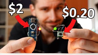
- This is Part 4 of the Do It Yourself (DIY) dyno build. In this video, we discuss improving the sensors used for detecting the rpm, modifying the display for a more modern look, how to range the gauges for the signals that we measure then we'll do a power run and examine the output. See Part 3 - Software (link below) on setting up the Dyno parameters.
Correction: When looking at the output curve, the X axis should be RPM1 and not time. I was so busy trying to get it to work, I overlooked that dynos measure power and torque against rpm.
DIY Dyno (Dynamometer): Part 1 - Mechanical
• DIY Dyno (Dynamometer)...
DIY Dyno (Dynamometer): Part 2 - Sensors
• DIY Dyno (Dynamometer)...
DIY Dyno (Dynamometer): Part 3 - Software
• DIY Dyno (Dynamometer)...
DIY Dyno (Dynamometer): Part 4 - Proof of Concept
• DIY Dyno (Dynamometer)...
DIY Dyno (Dynamometer): Part 5 - Moment of Inertia
• DIY Dyno (Dynamometer)...
DIY Dyno (Dynamometer): Part 6 - Gear Ratios vs. MoI
• DIY Dyno (Dynamometer)...
DIY dyno (Dynamometer): Part 7 - More Testing
• DIY dyno (Dynamometer)...
DIY dyno (Dynamometer): Part 8 - Moving Forward
• DIY Dyno (Dynamometer)... - Věda a technologie


how would you make this large scale, i have various engine sensors and engine parts i could use < fly wheel < crank gears etc
i want to tune my car and street tuning is dangerous
The mechanics of it would be a big undertaking. You could use a big drum and lots of math. The biggest I've seen was one made for a motorcycle. czcams.com/video/XUX_YWsECWs/video.html