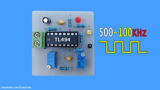
TL494 PWM Circuit

Vložit
- čas přidán 21. 08. 2024
- In this video PWM controller for inverter and dc to dc buck boost converter using TL494 IC, you can also use KA7500 IC both have same pinout.
This circuit consists of isolated voltage feedback with optocoupler and have current adjustment feature which can be used to make voltage and current controlled power supply. In my case output frequency is 36KHz which is very useful for high frequency inverter and high efficiency dc to dc buck boost converter.
Components required
TL494/KA7500 IC
PC817
10K pot
LED
100ohm, 150ohm, 1Kohm, 2.2Kohm, 4.7Kohm, 10Kohm
10nF capacitor
16-pin IC base
PCB
Circuit & PCB
drive.google.c...
#tl494 #pwm #inverter #converter
tl494 inverter circuit,tl494 inverter,tl494 pwm circuit,tl494
circuit tl494 pwm feedback inverter motor driver circuit tl494 pwm for moped
tl494 tutorial,tl494 inverter circuit
tl494 and 2sc5200 inverter circuit circuit tl494 pwm feedback inverter,tl494 and 2sa1949 inverter circuit
inverter 12v to 220v,tl494 inverter circuit diagram inverter
tl494 as buck boost converter tl494 buck boost converter repair tl494 buck boost converter
boost converter tl494 boost converter igbt tl494 buck boost converter tl494 boost converter circuit
tl494 buck converter tl494 buck converter power supply 3-15v tl494 buck boost converter dc to dc converter innocationic


Make inverter or buck boost converter with this circuit.
for more understanding about the circuit
Thanks for sharing
Keep up the good work
most welcome
Mind voice
Thanks.
Welcome!
Thanks.nice work. want to now if voltage feedback have aresistor or not .and were to conect courent séance.
voltage feedback have resistor and the current sense i.e. pin 16 of TL494 will connect to shunt resistor, also I am working on buck-boost converter which come soon.
Sir part two pls how to connection feedbacm wire in output pls pls pls pls reply 🙏🙏🙏🙏🙏🙏🙏🙏🙏🙏🙏🙏🙏🙏🙏🙏🙏🙏🙏🙏🙏
ok in second part all doubt will be solved
@@innovationic sir sir please reply how many day take I will waiting pls pls also adjust volt and frequency in 2nd part
@@innovationic very very thank you sir 🙏🙏🙏🙏🙏🙏🙏🙏🙏🙏🙏🙏🙏🙏🙏
may be tomorrow
@@innovationic very very very thank you I am waiting 🙏🙏🙏🙏🙏🙏🙏🙏🙏🙏🙏🙏🥰🥰🥰🥰🥰🥰🥰🥰🥰🥰
Connection of feedback and how to regulate output volt pls reply reply 🙏🙏🙏🙏🙏🙏🙏🙏🙏🙏
Through feedback we can adjust output voltage sir pls pls pls pls pls reply 🙏🙏🙏🙏🙏🙏🙏🙏🙏🙏🙏🙏🙏🙏🙏🙏🙏🙏🙏🙏🙏🙏🙏🙏
Diagram pls
Circuit is given in discription
drive.google.com/drive/folders/1exQcQxBfob6afOiGZqXyp5zO4PZ5YIeP?usp=sharing