Using the ULN2003A Transistor Array with Arduino

Vložit
- čas přidán 8. 11. 2014
- New version of this video: • Update 2024 ULN2003 Tr...
www.bristolwatch.com/ele/uln2...
ULN2003A Darlington Transistor Array with Circuit Examples
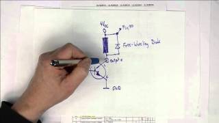
Unipolar stepper motor driver using ULN2003 driving PNP Darlington transistors.
Arduino Unipolar Stepper Motor Driver Board with Arduino Code
• Arduino Unipolar Stepp... - Věda a technologie


An excellent device, superbly explained. Clear speech and no music. Probably the best tutorial I've ever seen.
original video dont have the music for copyright algos manipulation...
Thank you so much for including the diagram at 7:15. I never would have thought to connect the pins for more current.
Just came across this video. Thanks! This was an excellent description of the uln2003's practical use. This helped me, as hobbyist, to understand its function and make a decision on its fitment for my project. Thank you for sharing your expertise! This helps folks like me who may not completely understand the data sheet and are looking for parts for our projects.
Man you are the best . Well explained . You have patients. All students love you. People like you make this world a better place. Thank you for the info.
Well done, love to see things explained down to circuit level and not just a pin in pin out of a IC.
Excellent discussion...clear, concise and visual. NOTE: I used to play the "pins" all the time.
Your video is 9 years old but still a gold (other than the cough, ha ah )
it is the best class of uln2003 i've ever seen. Great video.
Brilliant explanation, I am glad I came across this video as I was planning to wire up 8 2N3904 NPN transistors to drive a 4x7 segment display with a 595 shift register. Now I can prevent a headache with this beaut :)
Thank you for all of your videos. I've learned a lot!
Thanks Lewis! I'm just an electronics hobbyist, and had no idea this kind of thing even existed! This is going to make my current project cheaper, easier, and smaller - thank you!
Follow-up : I have another project where I need to control 7 solenoids, and their coils are rated for 12VDC @ 600mA... any suggestions for a similar chip that would be able to handle the higher current? I see there are some higher current chips, like the ULN2074B, but it doesn't have 7 channels... I have read that you can stack the channels on the ULN2003A, but have also seen that using multiple channels at once decreases the current handling capacity of each channel... Thanks for the instructional videos!
phrend
Go to separate transistors or MOSFETs. I have a number of videos and pages on the website related to that.
What a great little chip. Thanks for bringing it to us.
Thank you very Much Sir.
Your Explanation with Different Examples made it very Helpful
well done video, thanks for the clear, concise explanation!
thanks for making such detailed and skilled videos.
GREAT TUTORIAL !!! Love ULN2003 !!!! Thanx for Sharing this !!!
An oldie but a goody -- saved some time on investigating use of this part -- Thankyou
An excellent tutorial - clean and concise. Before I watched this video, I was having a tug-of-war with my hair :)
Thanks for the videos, helped me to use this transistor array
Btw:, I think your tea is ready.
Great video as always very well explained Thank you
Brilliant explanation! thank you so much!
Thanks Lewis! Great tutorial!
Thanks, explained in terms that i can understand
Cheers Gilbert
This was super helpful. Thanks
Concisely explained!!!
Now this was very usefull! I mistakently connected the other side of my relays (on side being connected to the ULN2003) to ground. Smarter Every Day ;)
But how it the relay grounded? since 24 V+ is on one side where are the ground? is the ground on pin 8 and common for the 5v and the 24 volt. what will happend if they have different power source like a usb on a rasbery on one side and 12 volt car battery on the other side?
best explanation I've seen
useful Examples especially paralleled outputs for higher power
More pages videos.
Using the ULN2003A Transistor Array with Arduino
Using the ULN2003A Transistor Array with Arduino
www.bristolwatch.com/ele/uln2003a.htm
ULN2003A Darlington Transistor Array with Circuit Examples
-----
Using the TIP120 & TIP120 Darlington Transistors with Arduino
Using the TIP120 & TIP120 Darlington Transistors with Arduino
www.bristolwatch.com/ele/tr3.htm
Tutorial Using TIP120 and TIP125 Power Darlington Transistors
-----
Using Power MOSFETS with Arduino
Using Power MOSFETS with Arduino
www.bristolwatch.com/ele/tr2.htm
N-Channel Power MOSFET Switching Tutorial
www.bristolwatch.com/ele/tr1.htm
P-Channel Power MOSFET Switch Tutorial
-----
Using PNP Bipolar Transistors with Arduino, PIC
Using PNP Bipolar Transistors with Arduino, PIC
Using NPN Biploar Transistors with Arduino, PIC
Using NPN Biploar Transistors with Arduino, PIC
www.bristolwatch.com/ele/tr4.htm
Understanding Bipolar Transistor Switches
-----
How to build a Transistor H-Bridge for Arduino, PIC
How to build a Transistor H-Bridge for Arduino, PIC
www.bristolwatch.com/ele/tr5.htm
Build a High Power Transistor H-Bridge Motor Control
www.bristolwatch.com/ele/tr6.htm
Driving 2N3055-MJ2955 Power Transistors with Darlington Transistors
-----
Build a Power MOSFET H-Bridge for Arduino, PIC
Build a Power MOSFET H-Bridge for Arduino, PIC
www.bristolwatch.com/ele/h_bridge.htm
H-Bridge Motor Control with Power MOSFETS
www.bristolwatch.com/ele/tr7.htm
More Power MOSFET H-Bridge Circuit Examples
Hi, thanks for the clear and concise description of the ULN2003. In the last example, 3 inputs and outputs were tied to increase the output current. Would it be possible to use three digital outputs from an arduino on pins 1,2 & 3 and combine the outputs of 14, 15 & 16. My hope is to provide three levels of current to an ammeter by turning pin 1 high then pins 1&2 then pins 1,2 & 3. I want to insert a printed face to an analogue ammeter to show three states driven by different input pins on an arduino. I’m just researching possible ways to achieve this.
Great explanation!! Thanks
Спасибо за предоставленные знания!)
thanks, it really helps a lot
Fantastic explanation.
Thanks for the video. I made my mind to make my own PCB for stepper motor control with the ESP32 rather than using the external PCB.
Note while the frame at 20 sec. shows a ULN2803 this video is about the ULN2003. Thanks.
Lewis Loflin well. Same thing except the 2803 has one extra Darlington pair lol. I use them with shift registers to run led arrays because the 8 pairs works out perfect lol.
Yes I noted that a few years ago. It is about the 2003.
Thanks sir most use full knowledge.
New version of this video is available: czcams.com/video/kKqjjp9HDX8/video.html
Very eye opening. Thanks
you have got yourself a subscriber
Unipolar stepper motor driver using ULN2003 driving PNP Darlington transistors.
Arduino Unipolar Stepper Motor Driver Board with Arduino Code
czcams.com/video/HTVYiLOY8SQ/video.html
Really clear video
Du bist immer top Bruder
Thanks for your videos I subscribed
Thanks a lot ,very well explain
Thanks for the info!
hi there, I have a question about the relays. where the negative terminal of the 24v go? I mean to power the relays ?thanks a lot
i have an opto-coupler to isolate my Micro and 24 V. I cant do common ground as i would loose isolation. shall i apply 10K resoster in series to 24V DC base Vin ?
Fantastic! Thank you.
GREAT VIDEO THANK YOU
Hello Professor,
I brd brded a single coil latching relay with 1000ohm into bases of 2n2222a's form arduino.
Then I triggered the relay with ULN2003A.
The ULN required 7V to power the relay coil and the 2n...'s ran fine on 5V rated coil.
Do I need to add R here somewhere?
Thanks, Donald
great video thumbs up
Did you say they invert the input?
Thought I was already subscribed. YT must have hit that toggle switch to ground on this circuit. Seems like Big Tech and the government have a Darlington pair in common with the Transistor movement.
That being said.
I’m just a resistor in this circuit called Life. Great content.
😅 😀 😂
Excellent - Thankyou
Good explanation
Awesome explanation! I have a question about parallel connection example: will it triple the input current drain from IN1 and IN3 also?
As per my understanding Yes
Thank You Sir!!
Excelent video
Hi Lewis, I accidentally burnt my ULN2003L chip on my oven board. I believe this controls my oven door lock (motor) and convex fan motor. How "difficult " is it to unsolder without causing other issues with soldering iron? Also..don't want to damage new chip when soldering. Thanks.
thanks for sharing
Thanks for a very informative video. Is it possible to use the ULN2003 to make a 12V LED strip fade in and out, by varying the input? (Similar to the Arduino 'fade' example)
+cubiq1 Yes just use the Arduino or PIC pwm, etc.
+Lewis Loflin Great. Thank you!
Excellent♥
Excellent
thank you for the video; what is the difference between the ULN2003A and the ULN2803AN, do they do the same ?
No they differ. Check the spec sheet.
good video :D i learn some things :D
In the last example when pairing in/outputs for higher current (1A), the current per pair in 100% load seems greatly reduced, I wonder if its possible to even drive 1A trough it?
I wouldn't do it. Simply use separate driver transistors.
Awesome!
when it comes to doing 120v lighting with relays, I've always cut the hot wire and attached that to both sides of relay contacts, leaving the neutral wire uncut. Is that dumb?
excellent
what is the stabilizing resistors.Can you explain please?
Im making an led cube with common cathodes, red green being the anodes , do you think I can PWM thought this chip to make the leds dimmer to brighter ?
+patprop74 Won't work you need common anode to switch to ground. Yes PWM can work then.
Hello Mr. Lewis, great tutorial.
One academic question --- when we parallel the outputs so as to draw larger current for larger loads, during the switching time of Multiple Outputs, would the earlier switched output get eventually damaged?
(I am referring to the time gap between (pseudo code) PinOne.makeHigh( ) and PinTwo.makeHigh( ))
In case they do not get eventually damaged, what is the thumb rule for such a time -- I mean, "for X microseconds Y times higher currents are tolerated", etc.?
The more narrow the pulse the larger the current within reason. It is heat dissipation one has to worry about. This does work but remember this isn't a high power circuit.
@@LewisLoflin oh okay, thank you so much for quick response!!
Thank you
One thing to watch out for is that there is a voltage drop (somewhere around 1 volt) across the darlington's CE junction, so that should be taken into consideration.
I've found it to be 0,5V but point well taken.
@@LewisLoflin I think it can vary dependent upon the CE current.
hi sorrie for this stupid quistion i happen to have a 4ch low input active high current darlington sink driver called TD62308APG i just cant figure it out cause a transistor have 3 pins but if you look the inside of this array the transistors have 4 pins and the ic have vcc and ground -5v recomended im fearly new in electronics if maybe you could just explain to me how it works or if its posable thanks for your time
Exelente
I'm actually researching a replace 18 descrete parts with chip now (6 channel).
Excellent! Thank you for talking about applications.
Just one question.... what is a "Pinball Machine"?
No but really.. thanks. Videos calculating beta and all that don't help when what I'm looking for is application centric.
how does uln2003a differ from uln2003
Is there a way to use the uln2003 for have bio directional rotation of a simple DC motor if so please describe.
+Ahmed Ishaq No one direction only.
can we do this by adding Logic gates to this circit where the flip flop may turn the direction of the motor? if so please enlighten us
Pin 9 is to be given Vcc. Will it operate if we ground it? 5:15 How is it working if it works?
Don't ground pin 9 connect to Vcc. It can be grounded as shown for a lamp test.
Can ULN2003 be used to drive more than six dc motors?
What are the possible options?
There more than six outputs, but be careful of motor current.
well the thing is i need to drive 128 dc motors simultaneously. So what would be the best option?
Is there a way to make these switch positive or can it not be done?
No. It can only switch to ground from +Vcc.
So you can leave pin 9 unconnected? It’s not needed right?
Yes unless driving a magnetic load connect to +Vcc.
In relay circuit . If 9th pin is not connected with the 24v supply what will be the result
There wouldn’t be any current flow.
Can I use ULN2803|Uln2003 to control solenoid valve using PWM|Analog write???
Thanks :)
Why are you using PWM to control a valve? Assuming this is an Arduino write a 1023 for 5V out to a driver transistor to turn on/off the valve.
+Lewis Loflin I want to control the pressure of double acting pneumatic valve and make it stable and also move it using ps3 controller
Thanks
if I connect one of the base input to 5v of Arduino...then the base current will be 1.3 mA ( (5-1.4)/2700) .. Am i right?
Close enough.
شكرا جزيلا
أتمنا ان يكون مترجم الى اللغه العربيه
can they switch AC? or only DC? i have to switch many 24V 100mA AC signals....
DC only. Use a triac for switching AC. These are used in small solid-state relays. See my page www.bristolwatch.com/ele/triacs2.htm
@@LewisLoflin thank you
What is the different when I connect pin 9 to ground or to volt? How the array will work?
Either leave disconnected or tie to +Vcc. Connecting to ground shorts out the drive pins.
@@LewisLoflin where would the ground be going for the components connected to the output side of the uln2003? Does the IC act as a ground with power going to pin 9 but also the components? I'm new to this hobby and am a little flabbergasted at how complex such small devices work... Amazing stuff! Also nice videos, been enjoying learning new things!
Do not connect 9 to ground you will ground the outputs. If driving a magnetic load such as relays, connect pin 9 to VCC.
@@LewisLoflin where would the ground be if not on 9? Does the ground on the input side act as ground for the outputs?
@@jeffreydoty8710 Yes it is common to both sides.
sorrie another thing it says NPN output stages and PNP input stages what does that mean
Don't remember that. The internal transistors are NPN. It can drive a PNP transistor if properly connected.
@@LewisLoflin okay thanks ill hook it up again and see how far i get
Like
Like♥️
Aaah those darlingtons, why not mosfets?
Mosfets take less power. UCC2776 - 18V 1.5 A to 3A peak per channel driver
That wasn't the subject of the video.
Ok :P
There are eight parts per channel but he only explained seven . . .
burned 2 uln2003 when connected 12V lamp with 12V voltage source in the way as is shown on this movie (lamp eg.),
+Pawel Wojcik What was the watt rating of the lamp? How many amps?
+Lewis Loflin there was 21W bulb 12V, never get more than 1.6A using this bulb on other 12V power source
That's almost 2 amps. Why not use a single transistor and a resistor?
wanted to steering it by pwm in few channels of uln2003, and then could rise and drop light saturation quite fluent
... Except that the photo shows an 18-pin DIP...
You're showing the photo of a ULN2803 (which has 18 pins, not 16) while talking about the ULN2003. Kind of confusing...
Look at it again it has 16 pins.
At timestamp 20 sec. I see an 18 pins device with the label ULN2803 on it.. At timestamp 1 minute I also see an 18 pins device, also with the label ULN2803 on it. => ???
For the rest of your presentation, you're indeed showing the diagrams and schemes of a ULN2003.
Apart from that, your video's are very interesting... :-)
You LOOK at it again, it as 18 pins in the first photo.
Open your eyes: the whole (very good, by the way) presentation (including the drawings) is about the ULN2003A, which has 16 pins and 7 darlingtons inside, while the photos of the device shown are of a ULN2803 which has 18 pins and 8 darlingtons inside. That is the confusion I'm talking about. Is it really that difficult?
OK I see it at 20 secs. but this is about the ULN2003. Thank you.
Your package have 18 pins!
The chip at the beginning is not the ULN2003.