EEVblog

Vložit
- čas přidán 19. 06. 2024
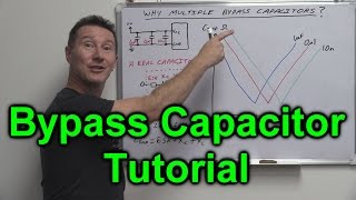
- An in-depth practical visualisation of how bypass capacitors work at both high and low frequencies.
Bulk decoupling capacitors vs bypass capacitors.
Capacitor placement and types are tested and the results examined.
How package inductance can have a large effect.
Loop area and what is means, it's impact on EMC emissions, and how currents flow in ground planes is demonstrated
Links: web.mst.edu/~jfan/slides/Archa...
Bypass capacitor tutorial: • EEVblog #859 - Bypass ...
Muntzing: • EEVblog #1081 - Are By...
Forum: www.eevblog.com/forum/blog/eev...
EEVblog Main Web Site: www.eevblog.com
The 2nd EEVblog Channel: / eevblog2
Support the EEVblog through Patreon!
/ eevblog
Stuff I recommend:
kit.com/EEVblog/
Donate With Bitcoin & Other Crypto Currencies!
www.eevblog.com/crypto-currency/
T-Shirts: teespring.com/stores/eevblog
💗 Likecoin - Coins for Likes: likecoin.pro/@eevblog/dil9/hcq3 - Věda a technologie


Potentially my favorite tutorial you've done! As a student, this was a difficult subject for me because it felt like every answer led to more questions. You've done a great job here at building the understanding of all the design aspects and seemingly mystic industry standards in this video. Excellent job, big thumbs up!
Thanks
What a wonderdul world, someone records such a useful video and serves it free of charge
Why doesn't this video have more views?! This has got to be the best capacitor tutorial I've seen. Before thiss I had no clue how important bypass cap are for digital noise decoupling. Coming from Arduino with a breadboard and basic electronics knowledge, I had no clue about how bad breadboards are for until I tried running a TFT @ 80MHz SPI clock. Your videos are a Bobby dazzler!
This video is a criminally underrated and wonderful demonstration in purely practical terms on how bypassing works
Definitely your best kind of videos.
Your are excellent at educating with demonstrations, without skipping the theories.
Thanks!
You probably dont care at all but does anybody know a way to get back into an Instagram account?
I was stupid forgot my account password. I appreciate any assistance you can offer me
@Landyn Kaden instablaster :)
@Bowen Marco thanks for your reply. I got to the site thru google and I'm trying it out now.
Takes quite some time so I will reply here later with my results.
@Bowen Marco it did the trick and I now got access to my account again. I am so happy!
Thanks so much you really help me out!
@Landyn Kaden You are welcome :D
Super helpful! I miss these sorts of videos.
Me too D=
missed you mean ;)
hopefully...
Awesome demonstration with low ripple and spike reduction. I have been an engineer for many years, but I have never ‘actually’ scoped out these thing with multiple capacitors, but rather just assumed theory and calculated numbers. Great video!
Dave, thank you!! This is the best explanation of bypass caps i have seen. I've tried to read the wiki and other articles but this is so super clear!
Awesome video as always Dave! Always wondered how those small components did their magic. Thank you so much!
This is priceless.
Always heard about loop current, EMI radiation regarding FCC and all that sort of stuff, but never seen it like this much detailed.
So much energy and research went into this absolutely great video! Thanks Dave!
This video is fantastic. To know what the bypass capacitor is for is one thing, to see its effect is something else. Brilliant.
Hands down the best demonstration I've seen on why bypass capacitors are needed.
Wow, I was just looking up bypass capacitors effect and saw your previous video about it and they were really helpful on understanding why certain capacitors are used and understanding their use.
Best practical demonstration of bypass capacitors, I've ever seen. *Thanks so much!*
I've never had the bypass capacitors explained this clearly before. Thanks. This really shed some light on the topic.
This video is incredible! Really helpful for the board I'm designing right now. Love these sorts of really practical demonstrations
I love this topic - Such a clear connection between theory to practise. Really well explained Dave. Cheers mate!
Thanks.
@Dave, what a fantastic video! I watched all 33 minutes and 34 seconds. Thank you for this video. PS: When you have this setup, please, could you try to add a ferrite bead into the circuit, just to see if there will be visible difference before and after the bead?
I always feel difficult when using FBs. From the power delivery view point, we need the power supply to deliver the current as fast as possible to satisfy the nsec, or even hundreds of psec rising/falling time. However, the ferrite beads slow down the current by acting as higher impedance in some high frequency domain. FBs simply dissipate certain amount of high frequency energy. If this high frequency content is exactly what the system needs, say your processor, we'd better not using FBs in this frequency domain. Choosing the right frequency seems to be the most important thing! But I also found FBs useful when designing a board using a given external AC/DC adapter, sometimes you have no ideas or no choice what kinds of switching noises would inject input your power system, leave the FB pads there on your board seems to be a good practice.
@@zhitailiu3876 Could not have said it better.
@@kodedude What if you routed to the capacitors first, to supply the high frequency switching power demands locally, but ran the ferrite to the power rail - thus creating a high frequency high impedance disallowing the full effect of the noise to get on the power rail?
Great video Dave, I loved it. As usual, you cut right through the BS and explained the concept better than any textbook ever could.
Man, I just love these hands-on (probes-on?) demos. Thanks, Dave!
Your videos come always with very rich and in-depth content, thanks for the effort!
You have amazing ease of passing knowledge. If you cannot explain it to a 6 year old kid, you don't understand it - so you do not only understand it but you just feel it!
Awesome video. Spent all day soldering 0805 100nF caps on my circuit boards. Nice to be reassured that it's worth it!
As Dave says, at High Frequencies the current returns in the ground-plane under the trace. A good way to think if this is that the trace and the ground-plane are two windings on a transformer. As current flows in one direction in the trace, an equal current flows in the other direction in the ground-plane. The trace and ground are magnetically coupled.
It can be shown by experiment that the current will even go through a resistor in the ground-plane under the trace rather than a short-circuit away from the trace.. Weird huh... Putting a nice big slot in the ground-plane makes the return current go all the way around the slot. The fields in the conductors don't cancel and radiate really well!
Slot antennas are built on that principle.
This is probably the best series about bypass capacitors that I have ever seen. Keep it up! I'm really enjoying your experiments! :)
Great video, Dave! Had no idea what a crazy difference that packaging makes.
Great stuff Dave! This should be very helpful as we are having some grounding (and most likely EMI) issues with our boards at work. We have some 5V stuff going on but the main culprits are the 48V solenoids being driven at various duty cycles. The PWM frequency is ~1.7kHz. We already have planned updates for better grounding on the boards, but it looks like we might be adding some additional capacitors as well. Just don't want to get too carried away and drive up cost as the 48V coils are power hungry.
Been noticing your videos have been the ones I’ve been watching more to learn about components. Threw in a FAT tap on that subscribe button. Thank you!
Good video Dave. Only thing I am missing in this story is (noise) decoupling with ferrites. Which is also an excellent and proven way to get rid of switching noise.
Awesome video.
This explains decoupling in a much more tangible and easy way than my years attending electrical engineering classes. I would enjoy a continuation of the series with a practical PCB example - perhaps designing a PCB and then measuring it the same way you did in this video before mounting decoupling and then measuring EMI impact as you add caps.
This was awesomeness, thanks Dave. Beautiful display, Iam just learning about basic things and I understood. Fascinating stuff my friend.
Thanks.
EEVblog very welcome
Great video! Really love the visual nature of it and the explanation! 👍
this was great! moar practical applications in the future pliz =D you really make it look easy to operate the metering equipment what a freaking legend
I love this sort of technical content, keep up the good work.
It is a wonderful video, but I just have one question, why would someone dislike this video? I read David's PCB Design Tutorial before my job interview, and it helped me a lot. Thank you, David.
Really fantastic video on bypass capacitors, very instructive with a beautiful test set-up and experimentation.
Never had much of an education and at 54 I'm now really enjoying learning why some of my day projects had problems and now inspired to get designing some more projects
That should be a included in every electronics theory course - very well explained and demonstrated.
Great stuff! I learn a lot from these videos. And get inspired to do similar tests on my own bench.
A video full of information! I Love it!
Great demonstration Dave. Your efforts are much appreciated
Thanks.
1Курс университета в одном ролике с практикой.
2 курс "2 vs 4 layer board".
Отличное пособие.
Не смог оторваться до конца!
This is a great demo. Makes heaps of sense and easy to follow. 👍👍👍
Thanks Dave, needed some fresh information about this, too many years without electronics.
One of the best tutorials deminstration ive seen
Best video in a while. Thanks Dave!
I would have killed to have a "Practical Application of Fundamental Circuits" that did stuff like this in school.
At least we have you filling in the gaps in our education. Thanks Mate!
EXCELLENT demonstration!
Thank you very much!
Great video and practical demonstration, Dave !!
If there ever was a case for a star button (next to thumbs up button) this video is it. Top quality content Dave!
Great video Dave and very timely for me, thanks.
This is awesome. Thank you, Dave!
OMG thank you so much you made my day! your videos are perfect for this quarantine. Thank you so much!
MUUUUITO BOMMMM !!!!!!! extremamente didático ! Parabéns pelo experimento !
This is the clearest video on this topic!
Great video, love these demonstrations!
This video is glorious, thanks Dave, best video I've seen about this subject.
I though this process was called squelching the signal or a version of a shunt... thank you for these videos so much more than what I have ever expected.
Love learning new stuff! And this is just what I needed! Thanks Awesome video
A nice demonstration there, Thanks :)
Good demo! 100MHz-ish seems to come directly from DUT which typically oscillates at a higher frequency to divide down to the 1MHz output signal.
This is one of the best videos in absolute.
I think I just learned more in this 30 minutes than multiple months in university... thank you very much Dave. I could tell that was a lot of effort, and these videos are super helpful.
Glad to hear. Might look like a lot of effort, but not really, pretty simple demo in the end.
@hardstyle905 Thankfully I'm not any longer. This is 5 years ago! Universities don't visualize what a bypass capacitor does like this, instead they make you write down the various math of capacitors in a hurried mater during lectures - and it's up to you to decipher your notes later and apply that to an application. I never said Universities are worthless or anything by the way, just that this visualization helped more than several lectures at the time.
@hardstyle905 I think Universities are trying to put more importance on that lately, which is a great thing. We had that as well, but it was always an afterthought or just 1 hour a week, where you had a very rigid syllabus of something - where a big report was due after it. I remember a lot of it was "connect this to that, go to oscilloscope and put in these settings, now print this screen, etc" instead of exploration and curiosity, or even understanding what was being done (often it was a scenario with the TA running around trying to fix the problems arising such as components being dead or something from the physical abuse of undergrads).
Great and simple explanation, Dave! I'd like to propose some extension to your test setup - to add "termination resistor" in series with osc. output: same as for hi-speed lines to correct impedance matching.I suppose that it should be visible on scope too.
Alan w2aew done a similar demo on this as well.. great job !
Wow I didn't know bypass capacitors made such a big difference. I always knew and sort of had a rough "feeling" for how much is enough from a circuit to circuit basis, but I never imagined they made this much of a difference.
I did not finish watching but can't help myself: KILLER VIDEO! People need to know!
Great video. Enjoy activating the little gray cells.
This is the greatest video ever. Thanks so much!
This is such a great video! I've never seen this done before. How little change in ripple when the bulk cap was connected at the bench supply! (16:11)
It would also be interesting to see what the output at the power-supply looks like when moving the bulk cap around.
Always love these videos 👍🏻
Wow, awesome video, that helped clear some things up for me
This is the real GOLD! Thank you
Excellent demonstration
You are killing yourself to teach something to us, I bow to you. and also i like to be in your super equipped laboratory.
Really nice 😊😊😊
Even I understood this and I don't have any knowledge about this at all. Please make more videos like this😊
Super great video, efficent for understanding. thanks a lot
Perfect video. Huge Thumbs UP!
Awesome video, Dave. I really liked the approach of setting up the experiment and adding caps of different values in different locations. Adding the SA at the end to drive the point home was a nice touch.
I would definitely like to see more experiment based videos to illustrate some of the why behind circuit design.
Excellent as usual.
This video is a tad “long format” for me
But I applaud you
Actually seeing a simple circuit
And watching the shit go on a proper O scope
Just....really is a good way for me to learn
Thank you
Excellent demo!
awesome demo again
Very nice class, Master!!
Dude you’re hilarious 🤣. I really enjoy everything piece of info you provide.
Not long ago, I found a video that explained power factor correction well and the use of the caps for correction. Basically, the cap sink/sources in-rush currents for the inductive transitions, in this case to avoid pumping the power grid. I realized then that the bypass caps could in fact be for similar purpose. Nice to see that confirmed. I see they both dampen the pumping of the lines but also flipped to the other perspective they provide instantaneous current for digital pins which are not as forgiving of lags as motor windings are.
Great explanation. Cheers!
Great video and explanation, thanks a lot 😊
Great Video, Cutting the ground return plane as close to original track might help to force current return to much smaller path. This might help in reducing high frequency impedance and reduce loop path
Thank you so much again for this awesome video
A good example to visually test and see why you need bypass caps: programming serial memory (such as SPI). In my lab, I have found several parts that when it does a self-erase, the IC drops the VCC so low that it resets the board's micro. With a large bypass cap, it works just fine.
Excellent video! Thanks very much
Thank you Dave.
Fantastic video, man!
Great explaination really enjoyed it well put and very helpful thanks
what and excellent video. Thank you so much. Very informative
This is very good. More of this!
Welcome back to real electronics Dave :)
it was so VISIAL!!! THANKS A LOT!!!