Introduction to power factor correction (PFC) and control

Vložit
- čas přidán 9. 07. 2024
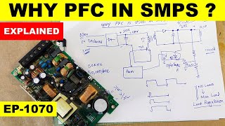
- An intuitive explanation of what is power factor, CCM type power factor correction (PFC) circuit, border line PFC circuit and CCM PFC without sensing the input voltage.
Key papers discussed in the presentation are:
Ben-Yaakov, S. and Zeltser, I., PWM Converters with resistive input. IEEE Trans. Industrial Electronics, 45, 3, 519-520, 1998.
www.ee.bgu.ac.il/~pel/public.htm
Ben-Yaakov, S. and Zeltser, I., The dynamics of a PWM boost converter with resistive input. IEEE Trans. Industrial Electronics, 46, 613-619, 1999.
www.ee.bgu.ac.il/~pel/pdf-file...
Ben-Yaakov, S. and Zeltser, I., PWM converters with resistive input. Power Conversion and Intelligent Motion, PCIM-98, Nurnberg, 87-95, 1998.
www.ee.bgu.ac.il/~pel/pdf-file...


Thank You Professor! I've learned so much from you over the years about magnetics, power electronics, etc., but this information had to be the most valuable to me at any given time. Not only did you concisely explain the innerworkings of the Best CCM PFC ICs on the market, but with your design, you've shown me that I'm on the right track. I've already got the PNP current mirror in my design for the math, was just going about it differently. FINALLY! Someone explains K constant in detail and that multiplier down to component level .
🙏😊
Dear Professore, your lessons are for me a gold miner, thank you for all!!!
😊thanks
Prof Ben Yaakov, a wise man once said that if you can't explain complex problems in a simple way,
you do not fully understand the problem.
You are by far one of the more gifted lecturers around.
First giving the high-level picture and intuition to a problem with minimal math necessary.
Also, your understanding of what a student can grasp at first glance and what must be repeated several times using different approaches for different people in the listening crowd shows your passion for teaching and educating.
Your lecture style is very similar to Grant Sanderson (A.K.A 3blue1brown).
Thanks Shahar, comments like yours keeps me going.
Prof Ben Yaakov, thanks for your reply!
BTW, are you planning to make a video on bi-directional power supplies?
They seem to be the preferred charging topology in the electric vehicle market.
Albert Einstein
Prof. Yaakov, thank you for this wonderful session.
Thanks for note
I have just discovered your channel, and I'm so glad that i have.
Love your videos, you are a great teacher.
God bless you.
😊🙏. Enjoy the videos. By now there are many.
Absolutely great explanation Sam!
Thanks
Excelent! Thank you Dr. San Ben Yaakov.
😊
Thank you for sharing your knowledge, it has been of great help.
Thanks for comment
Thank you professor, I've been wondering the working principal of Infineon's CCM ICs, the thoughts really haunted me until today when your explanation really lighten me up.
👍🙏
Another great video thank you!
Thanks again.
Amazing lectures. Thank you so much.
Thanks
Hello, and thank you again for your videos.
Thanks
You are correct. In Boost Vo>Vin
Thanks a lot professor ... I've benefited a lot from your lectures.
Also it will be great if you make a lecture or two about phase shifted dual active bridges, because as you know they are dominating now in a lot of applications,
Regards
Thanks for comment.This might be useful to you:
www.ee.bgu.ac.il/~pel/pdf-files/conf130.pdf
10 x THUMBS UP! Very nice subject and presentation! Thank you!
Thanks.
Sir, I'm wrong if I assume that this is a subject for master classes at Electronics Faculty? I didn't encounter this approach for PF correction when I studied Power Electronics during the 4th and/or 5th year at faculty.
This is my way. I think the most important part of engineering teaching is to convey the gist of the subjects for in depth understanding. Analytical derivations and equation secondary these days considering the software we have
Great video sir. Thanks
Thanks.
I have one question:
In-order to change the current waveform the PWM changes the Duty Cyclebut then the gain of the boost converter also changes.
Does making the Current to follow the same waveform as the rectified voltage assures me that the output voltage will remain constant?
The changes in the duty cycle are minute, just to overcome the change in voltage drop on parasitic resistance due to the varying current.
Professor..
Wat is the different between power factor in power system and power electronics
Well done sir.
🙂
Hi Dr Sam...
May I know what is the advantage using this kind of power electronic PFC compare to AC capacitor bank
THD is much lower
Do any modern power supplies use DSP's to replace a lot of the analog circuitry (filtering, feedback for output regulation, and generating the PWM signal for good PFC, etc)? Or is this still in the domain of analog specialty power-supply controller IC's? Dedicated analog controller IC's can probably operate much faster than DSPs (maybe?), and allow using smaller/cheaper inductors which make up a good portion of the cost of a SWPS. There are reliability issues with DSP's too (software bugs, random bit errors in an electrically noisy environment) that might make them unsuitable.
Hi Jess, thanks for comment. Yes, digital control is paving its way into the power electronics arena. Advantage are seen when the processor is not just mimicking the analog controller but when when real time logic decision are incorporated.
Would you please share your comment at the LinkedIn group ( www.linkedin.com/groups/13606756 ) I have recently started? Thanks.
Hi Sam, You have talked about Boost PFC, but what about Buck PFC ? In what range of power is a Buck PFC recommended to use ?
There is a problem with a step down. You will not get any current for input voltage below the output voltage.
Ohhh, I see, so there is higher THD and hence RMS currents... so its power range is low...
Correct.
Thanks for ur videos.
It will be very helpful if u can post the more lecture on transformer design calculations
Have you seen this:
czcams.com/video/3nfqBzPMknY/video.html
?
thanks you for replying.....
request to share some more details for better understanding the hf transformer design.... please suggest any book that can provide basic details...
Transformer and Inductor Design Handbook, Fourth Edition (Electrical and Computer Engineering) 4th Edition
by Colonel Wm. T. McLyman
Thanks you.....
I have a doubt how frequency can effect mos capacitance....
I have one question: what is the actual limit on the current ripple in the inductor in CCM PFC ? is it possible to use a controller intended for CCM PFC while the current is discontinues ?
Hi Moshe, the transition from CCM to DCM is when the p-p ripple is equal to the DC value. There is usually no control problem when the converter moves from CCM to DCM but if only DCM is expected, phase compensation tuning will improve performance.
Hi , thank you for the reply, but this is not my question. i want to work in DCM (with high ripple current like boundary mode even at full load), but at a fix frequency. The question is will it be possible to operate properly with a control IC that supports CCM PFC ?
Sam, are there more lectures about PFC in your chanel, i cant find anything more?
czcams.com/video/Jv2JVorAeiE/video.html
I was wondering what will happen if we replace the AC input with DC one , for e.g instead of 240v AC we supply 345v DC , how would this circuit will response ?
Normally it should work OK current in phase with voltage🙂
@@sambenyaakov thanks for reply soon I will be testing it , and will let you know what happens 😄
Sir, thanks for the video.
Can you post some lectures on active front end or suggest some handbooks on it.
Thanks for comment. Will try.
Can you make a video on Half and Full wave rectifiers and the method of assumed states?
wil try
Sam Ben-Yaakov Thank you. Your videos are excellent.
Hi, could you do a lesson on ZVS phase shift full bridge converters?
There is some information at czcams.com/video/w4cxLPl2Wsg/video.html . Will try to deo a specific one.
Thank you very much!
which one is widely used today?
I guess the Boost type but tort pole is getting momentum.
The goal is to to build a PFC unit operating at full ZVS at a fix frequency , and the high ripple current (with some negative current) is needed for that . but there is no control IC to support it.
Perhaps these will be of interest?
www.ee.bgu.ac.il/~pel/pdf-files/pat17p.pdf
www.ee.bgu.ac.il/~pel/pdf-files/conf123.pdf
can you send me this slide in the video, plz?
Sorry. This was recorded sometime ago I am unable to locate the slides.
Sir, after 1:38 you defined Power Factor=Real Power/Apparent Power, which followed by V1rms.I1rms.Cos(theta)/Vrms.Irms. However, my confusion is, is that Cos(theta) suppose to be the power factor?
May be I got it wrong but I just want to ask, what is the difference between your definition to this definition:
Real Power=Vrms.Irms.Cos(theta)
Apparent Power=Vrms.Irms
Therefore,
Cos(theta)=Real Power/Apparent Power
Power Factor=Cos(theta)=Real Power/Apparent Power
Real Power is = I1rms*V1rms(cos(theta)
@@sambenyaakov So that "cos(theta)" is the Power Factor right?
No. The power factor is as defined in video. In the PRIVATE case without higher harmonics it converges to cos(theta)
Thanks Prof. Sam Ben-Yaakov for clearing my doubt.
Looking forward to learn more from your videos Sir.
10:06
??
@@sambenyaakov sorry, its just a timestamp for me to resume when i come back to this video. Apologies!! Your content is great and i applaud you for what you do for the community👏
@@srini1635 For a moment I thought you found a bug😊Nice watch marking method