Electronics Tutorial - Common Power Factor Correction methods

Vložit
- čas přidán 24. 06. 2020
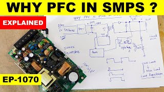
- #78 In this video I look at some of the common methods for correcting a poor Power Factor. I analyze the two main issues - the phase shift caused by adding reactive linear loads but also the current distortion caused by non-linear loads and afterwards I look at the common ways these can be handled.
Video on measuring power factor in LTspice: • LTspice tutorial - Mea...
Special Thanks to all my supporters on Patreon! Especially @afiskon !
If you liked this video be sure to check out my other videos and you can also subscribe to be up to date with all the new ones!
If you want to support the creation of more and better videos please consider checking out: / feszelectronics - Věda a technologie


Great one ... You summarized it professionally
He is master in Ltspice and simulation, I like your video too walid :) you can work more on LTspice too
Congratulations .. !! just simple and easy to understand. Why didn't my teachers teach it to me this way?
Such a great video!
Thanks so much! You really show how complicated concepts can be shown easily! That is what is needed in education nowadays! No academic ego and ridiculous difficult papers to read for the sake of publishing!
Congratulations
I often wondered how PF was correct. Absolutely fascinating and clear, many many thanks.
Nice video, quite confusing see the PFC with electronics at the first time, but this video is clear and simple.
excellent demonstration of power factor issues with really good real examples! Many thanks!!
Thank you, very informative!
Brilliant way to present it!
excellent description
now i understand better the power factor correction method
Excellent. Very well explained. I would love to see a part two where you look in depth at some commercial implementations.
Very professional video! Thanks for your help figuring out why BOOST is required for PFC. You save my hair a lot.
So good explanation and examples!!! :)
love your work nice
Brilliant explanation!
Thank you so much!!!
Great tutorial, thanks for sharing!
Great!! Really good explanation!
great vid buddy! helped me a lot!
Awesome explanation!!!
Excellent work 👏 👍
From the explanations I have watched so far, this one is the best.👍👍
Awesome and cool explanation 👌👌
Awesome video! THank you!
Excellent work 👍
Excellent video. Hats off. 🇲🇫
Instead of using a passive inductor(also called a choke), you could also use something called a gyrator. Also called an active inductor.
Probably not as efficient as the switching PFC version, but at least you don't need such a big inductor.
Maybe also nice to add is when you're supposed to officially use PFC. There are some regulations for that. But basically for consumer electronics everything under 75W is fine (very rough, there go a lot of details into that)
Nice video as always 👍🏻
A gyrator? Please enlighten me as to how one would go about using a gyrator in a PFC.
Very good video as always, thanks a ton for your efforts. But one suggestion is to show us what have you connected using a circuit diagram whenever you are using circuit demo so that newbies me can follow you properly.
Fantastic explanation .. Thank You for sharing... Cheers :)
Very good sir
Exellent explanation!!!
Glad it was helpful!
Many thanks Sir
very nice
very good.
Thanks a lot for the wonderful explanation, if it is possible to demo this circuit that would be great.
Thanks for the Video, was helpful. Could you please provide calculation of L and C in passive PFC?
Sehr gut
👍👍
Thanks
Hi Dear.,
Thaks for your effort to do the best of this point in youtube.
but my Question is about Active PFC case,
l had a IR2520D IC Model for Ballast Design but it has 0.6 PF Ratio but l need to increase its PF ratio to acceptable level such as 0.9 and over.
How can l do that with your support?
Thank you for your explanations.
One question regarding EN61000-3-2 standard:
How can I measure (plot) a curve Y= normalized harmonic current = f(x), with x = Harmonic number, using LTspice ?
Thank's in advance
Udo
Can you do something with totempole PFC with control logic?
Great Video, I am working on simulation of EV charger and being a new user of LT spice is facing the problem in achieving the upf operation of AC-DC stage which utilize Current Source Rectifier. Would help me a lot if you could make a video on its simulation.
Which model using oscilascope
Measuring the power factor of my PC with one of these Aliexpress power meters and it gives me around 0.7. Wonder if it is really that low because I have a bad power supply in the PC, or the power meter is not measuring it correctly.
Don't know what i'm doing wrong, but i can't see the power factor in my error logs :/
EDIT:
Alright, got it. Of course you can't see the PF when you do the .four operation on the chokes current :)
When a baby is born the doctor should also hand over an oscilloscope so that the child can understand electronics better when they grow to adulthood.
can you share the LT spice files for this
V2 is 600 Hz??
I changed it to 50 Hz, not happy anymore!!
why the electrolytic capacitor didn't explode
I was using 2 in series with the same polarity interconnected: +- to -+ ; this way the group behaves like an unpolarized capacitor. If this is what you are refering to
which color is which current? PLEASE LABEL THEM IN THE CIRCUIT!! or at minimum SAY WHICH COLOR IS WHICH.
Yeah, okay, HOW DOES IT WORK! here's my understanding.
Problem statement: A simple rectifier into capacitor power supply draws current only when the incoming sine wave happens to have a higher voltage (plus 2 diode drops) than the capacitor. At that moment, the capacitor starts charging and its effective resistance nearly zero thus current demand is very high, but only for a few milliseconds.
Solution statement: Find a way to spread out that spike that happens 120 times per second; find some way to extract energy from the entire sine wave not just the peaks.
The magic smoke is a FLYBACK regulator; known here as a boost regulator but it depends on the flyback effect of the inductor. This is the same phenomenon that generates the spark in your gasoline powered internal combustion engine.
For a few microseconds, the inductor is *shorted to ground* which seems like a bad thing but while shorted to ground it is building a magnetic field. Then you suddenly open that path to ground.
The magnetic field starts to collapse. It wants to push electric current in the same direction that it has been flowing. What is special is that it does not care about voltage; it will push X number of electrons up a very steep hill if necessary. So, even though the capacitor already has 300 volts on it, and you charged the inductor at a moment where the incoming sine wave had only 20 volts, when you interrupt the ground path, the inductor will push 20 volts no matter what; making a spark if it needs to. It pushes that 20 volts right onto the 300 volts already on the capacitor and THAT is how you glean energy from the 20 volt (or any volt) portion of the incoming sine wave and scoop it up on top of your storage capacitor.
Detailed nuance: We don't actually fully charge the inductor, that would be bad, and we don't completely dump the charge either. So we "top off" the capacitor with these little impulses that RIDE the incoming wave.
It is by its very nature current limited since the thing that charges the main storage capacitor is the FLYBACK impulses from the inductor.
The crossover distortion will happen because at some low voltage part of the sine wave there just is not enough TIME to charge the inductor. (RL time constant) and consequently even with nearly 100 percent duty cycle you cannot effectively boost to the 300 volt capacitor.
Conversely, when the incoming wave is at its peak, we allow the inductor to conduct for only a few microseconds; it doesn't need much high-voltage pulse to charge its magnetic field.
Flyback and boost converters are not the same. In a flyback converter current never flows simultaneously in the input circuit and the output circuit. Energy is stored in the inductor via the input winding when the switch is ON and then delivered via the output winding when the switch is OFF. In a boost converter energy is stored in the single-winding inductor when the switch is ON, but when the switch turns OFF current continues to flow from the input source while the energy that was stored in the inductor is delivered.
Whether or not the inductor is fully discharged each switching cycle depends on the design. Some designs use discontinuous currrent mode throughout the full input half cycle (i.e. the inductor is fully discharged each swithcing cycle). Others operate in continuous inductor current mode (not fully discharging the stored energy each switching cycle) for part of the AC half cycle but go to discontinuous current mode for part of the cycle. Operating in discontinuous mode has some disadvantages but avoids the "right half-plane zero" in the transfer function. You cannot compensate for an RHP zero like you can a left half-plane zero. You have to cope with it by pushing it to where it doesn't cause instability and that means accepting poorer dynamic performance. If the switching frequency is sufficiently high that isn't a big problem but does have to be considered.
It doesn't matter how little energy is stored in the inductor when the switch is ON, it will be delivered to the load when the switch turns OFF. It has nowhere else to go. The exception would be if the amount of energy stored is so small that it is 'eaten" by switching losses.
Two things are critical to active power factor correction.
• The "instantaneous" current must be _directly_ proportional to the instantaneous input voltage. "Intantaneous" isn't quite the right term. It is more a matter of the current during each switching cycle needing to track the input voltage. The current near zero crossing needs to be low. The current at the peak of the AC half-cycle needs to be "maximum" for the operating condition.
• The _average_ input current over the full AC cycle (or longer) must be _inversely_ proportional to the average AC input voltage. This is because of the negative input resistance characteristic of a switchmode converter.
You need a sleep man.
Naw, it's ok; that's just how my face looks. Maybe the lighting isn't helping either.