Good Crystal Radio

Vložit
- čas přidán 6. 07. 2024
- This is the best crystal radio I have made so far. It is based on a design described by By Al Klase, www.skywaves.ar88.net/xtal/PG...
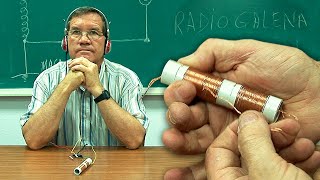
It consists of a single coil, but thanks to the intermediate sockets and the fact that part of the coil is used as an antenna-ground circuit, great sound power and great sensitivity are achieved. The coil cylinder has a diameter of 104 mm and a 17 m long wire has been used.
Everything is chosen to obtain the best result: the wire, the capacitor, the diode, and the size of the coil cylinder:
- 0.5 mm thick copper wire, insulated, giving it a total thickness of 1 mm. This insulator keeps the coils slightly separated and increases the quality of the coil.
- The variable capacitor that I should have used was a 320 pF one, but I used a 400 pF one in the assembly, which is the best I had and it was very good thanks to its ceramic insulators.
- The diode is a Schotty diode (BAT48), which provides a lower voltage drop than germanium diodes and also has greater sensitivity.
- The coil cylinder has a large size (104mm), and the ratio between tube diameter and winding is 2:1, which is not far from the ideal 1:1. It is purchased at a hardware store and is a piece that is used in smoke evacuation ducts. They are actually two pieces glued together.
- And, of course, high impedance headphones are essential, in this case one of 3200 ohms.
As for the operation, I manage to pick up more chains than with any of my other radios. I have not found improvements in terms of sensitivity and selectivity when connecting the clamp to the other sockets. I suppose they will be useful for certain weak signals.
The cable is obtained from a 21 m roll of UTP cable used for local computer networks. To unbraid it I used a cordless drill tool, with speed regulation. Otherwise it is very difficult, if not impossible, to do so for long cables like this. One end of the twisted pair is tied to a fixed point and the other end is attached to the tool, keeping the cable taut while the drill tool is operated.
The components are:
20m rooftop antenna
17 m of 0.5mm insulated cable
House electrical system ground
Coil with 53 turns on a 104 mm plastic tube, with taps on turns 5, 10, 20, and 30
400 pF variable capacitor (the calculations of the number of turns were made for 320 pF, but 400 also works)
Schottky diode BAT 48
3200 ohm headphones
Scheme:
mega.nz/file/8YpDXbQT#ng6Gxoh...
SPANISH
Esta es la mejor radio de galena que he hecho hasta el momento. Se basa en un diseño descrito por By Al Klase, www.skywaves.ar88.net/xtal/PG...
Consta de una sola bobina, pero gracias a las tomas intermedias y a que parte de la bobina se usa como circuito de antena-tierra, se consigue una gran potencia de sonido y una gran sensibilidad. El cilindro de la bobina tiene 104 mm de diámetro y se ha usado un cable de 17 m de longitud.
Todo está elegido para obtener el mejor resultado: el cable, el condensador, el diodo, y el tamaño del cilindro de la bobina:
- El cable es un hilo de cobre de 0.5 mm de grosor, y aislado, lo que le da un grosor total de 1 mm. Este aislante hace que las espiras estén un poco separadas y se incremente la calidad de la bobina.
- El condensador variable que debía haber usado era uno de 320 pF, pero he usado en el montaje uno de 400 pF que es el que tenía y era muy bueno gracias a sus aislantes cerámicos.
- El diodo es un diodo Schotty (BAT48), que proporciona una caída de voltaje menor que los diodos de germanio y tiene también mayor sensibilidad.
- El cilindro de la bobina tiene un gran tamaño (104 mm), y la relación entre el diámetro del tubo y el bobinado es de 2:1, que no está lejos del ideal 1:1. Está comprado en una ferretería y es una pieza que se usa en los conductos de evacuación de humos. En realidad son dos piezas pegadas.
- Y por supuesto los auriculares de alta impedancia son fundamentales, en este caso uno de 3200 omios.
En cuanto a la operación logro coger más cadenas que con ninguna de mis otas radios. No he encontrado mejoras en cuanto a la sensitividad y selectividad al conectar la pinza a las otras tomas. Supongo que serán útiles ante determinadas señales débiles.
El cable está obtenido de rollo de 21 m de cable UTP del usado para redes locales de ordenadores. Para destrenzarlo he usado un trompo de mano, con regulación de velocidad. De otra forma es muy difícil, si no imposible hacerlo.
Los componentes son:
Antena de 20 m en la azotea
17 m de cable aislado de 0.5
Tierra del sistema eléctrico de la casa
Bobina de 53 espiras sobre un tubo de plástico de 104 mm, con tomas en las vueltas 5, 10, 20, y 30
Condensador variable de 400 pF (los calculos del úmero de espiras se hicieron para 320 pF, pero con 400 también funciona)
Diodo Schottky BAT 48
Auriculares de 3200 omios
Esquema:
mega.nz/file/8YpDXbQT#ng6Gxoh... - Věda a technologie


Cada vez nos presenta mejores radios!!!😂
Very nice. Thank you.
Que bueno.!!Gracias por el aporte.😊
👏😎👍
👍🥰 Great Project
Increíble, Eloy!!
The coil is also inside the form?? Who would you wind it?
@@chrisb3989 The wire of the coil is only outside the cilinder. I wind it by myself.
@@RadioDeGalena thanks for the explanation I thought you had said there was an antenna coil winding (loose couple) inside the coil form. Congratulations that is a fine looking piece of work.