Arduino Project-Self Balancing Robot

Vložit
- čas přidán 8. 09. 2024
- Arduino Project-Arduino Self Balancing Robot
BAKON SBK 936D+ Adjustable Temperature Soldering Station: goo.gl/Q43wrm
The Best 3D Printer and DIY Tool Flash Sale: goo.gl/jx8Pc3
Gearbest Summer DIY Video Contest DIY Tool Best Deals:goo.gl/f57DD2
GearBest: Online Shopping - Best Gear at Best Prices: goo.gl/4wY4qU
In this Arduino Project Tutorial, I Built Self Balancing Robot with Smartphone Control using Arduino Microcontroller.
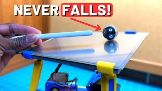
This Self Balancing Robot is a Two-wheeled Robot that balances vertically using a closed-loop algorithm. This Self Balancing Robot Features various modes like Position Hold, Simple Mode, Rise Mode and Joystick Control. This Robot is controllable by a Smartphone device or a Transmitter. Self Balancing robot uses data from the Accelerometer and Gyroscope to correct its orientation and position.
Instagram- / shinedjar
Facebook- / rztronics
Twitter - / rztronix
Code and Schematics:
github.com/mah...
Parts Used:
2 x NEMA 17 Stepper Motor-s.click.aliexpr...
2 x A4988 Drivers-s.click.aliexpr...
Arduino Nano-s.click.aliexpr...
Lipo Battery-s.click.aliexpr...
HC-05 Bluetooth Module-s.click.aliexpr...
GY-521 Module-s.click.aliexpr...
Prototype Board-s.click.aliexpr...
10cm Wheels-s.click.aliexpr...
M5 Rod-s.click.aliexpr...
Angle Brackets-s.click.aliexpr...
Screws and Nuts-s.click.aliexpr...
s.click.aliexpr...
Music-
Classic by Joakim Karud
• Classic (Loudness & Cl...


most people who watch content like this are very interested in how this is actually made, so if you could go through more technical details about the arduino shields used and the code and the wiring itll be much more appealing
Yes! Please!
Agreed.
I agree,my guy please get to the details
I made this robot.I did it.
@@pritigangavkar2898 Here's your medal 🏅🏆
I love the video quality. Seems somewhat professional. Please post more consistently if you want to succeed at CZcams, bc I know you would
Technical & Mechanical Guruji BC = because
@@UTechTuberdude
What does bc means?
@@edgaromarreynatorres3940bc means because
Try adding PID transfer function to avoid the wiggling movement. Than you will get smooth balancing. Great project btw!
How will the integral part help?
Damn geniuses,what I'm I doing here
@@isaacprosper6295 error_prior = 0
integral_prior = 0
KP = Some value you need to come up
KI = Some value you need to come up
KD = Some value you need to come up
bias = 0 (see below)
while(1) {
error = desired_value - actual_value
integral = integral_prior + error * iteration_time
derivative = (error - error_prior) / iteration_time
output = KP*error + KI*integral + KD*derivative + bias
error_prior = error
integral_prior = integral
sleep(iteration_time)
}
Really simple
edit: thats pseudo code btw
GOD JESUS TOLD US TO LOVE GOD AND TO LOVE ONE ANOTHER! LET'S NOT DESTROY THIS WORLD! NO WAR!!! БОГ СОЗДАЛ ТАКОЙ ПРЕКРАСНЫЙ МИР! НЕ БУДЕМ РАЗРУШАТЬ МИР! ПОЛЮБИМ БОГА И ВСЕХ ЛЮДЕЙ! НЕТ ВОЙНЕ!!
@@finnbschGOD JESUS TOLD US TO LOVE GOD AND TO LOVE ONE ANOTHER! LET'S NOT DESTROY THIS WORLD! NO WAR!!! БОГ СОЗДАЛ ТАКОЙ ПРЕКРАСНЫЙ МИР! НЕ БУДЕМ РАЗРУШАТЬ МИР! ПОЛЮБИМ БОГА И ВСЕХ ЛЮДЕЙ! НЕТ ВОЙНЕ!!
a lot of builders on YT need to learn from your video quality
Balances a lot better than the Boeing 737 MAX.
69 likes and no comments
69 likes and no comment
@@mr.boombastic8612 Can you not delete comments?
You realise it wasn't a balance issue that caused two of them to crash.
Kimmo Too soon?
now add follow me function, so that i can keep it as a pet
Exactly everyone's thought but unfortunately, that will have unexpected results and accidents, especially in public. Honda already has that in a following motorcycle. See here: czcams.com/video/Okf283Ct-NY/video.html
For some reason, this video looks very aesthetic and professional. Keep up the amazing work. Subscribed!
the shematic is wrong, the bluetooth only get voltage, and nothing more
Bravo (in french) ! Could you please add a picture of the pcb after all soldering is done ? This will be very helpfull for me who is not a great electronician ! Thank you very much.
Nice video quality and excellent job
now this is how u make a video , keep it up mate
please post more!!!! amazing production quality!
More flux and a little bit more heat and you will be pleased, great quality right here!
I love this video because the video quality is super and the song and sound make us to listen to it and the project is awsome so all the best to future
Nice to see that someone successfully repeated my project! :)
BTW why turn right/left is not on the video? You got some issues with that?
Can you describe the design and the function of the modules briefly ? That would help attract more views, I would prefer some technical details.
Do you guys thing electronic pieces we use for every electronic device can be refined and built differently with more efficiency in some way? Asking as a noobie. They were invented by really competent people but aren't us too accommodated to their efforts and that is making it more difficult to get a home labor robot?
Now how do I make it autonomously follow me around so I don't have to carry multiple shots to my friends?
Great. All you need to do now is make it 1 wheeled.
Awesome job! I'm working on a balancing robot myself at the moment. Still stuck in the math though. My approach uses 15 state variables in the model right now :'( But I'd really like to keep things like wheel inertia in the picture; I think my MCU is fast enough to handle it.
Excellent job but I have a question what is the Spécifications of the capacitor ?
Please try to add a proximity sensor to this. Hope you will do it.😊
I feel like I'm watching a chef cook a gourmet meal
It is not complete Schematic, bluetooth pin conection are not shown there
Yup - it's being powered but not used - very confusing :-(
Froud
I think there is a mistake in the schematic image, you are supplying the arduino 12v from the 5v pin and getting 5v from the VIN pin which should be the other way around ( you supply 12v through the VIN pin and you get 5v from the 5v pin)
Nice but you should add a turning function with the motors
Yeah if you can combine this part with pieces of an autonomous arduino car that'd be way better
I really like it. Hope for more young people can see it and take out more Idea.
beauty project ¡¡¡¡
woah woah easy on the soldering iron flexing haha :D great vid
Excellent job done. Very neatly explained all the stuf
can we use tt motors instead of step motors????Because tt motors are cheaper than step motors...
How does the bluetooth work if it's not connected anywhere?
it states that it's connected to TX and RX on the documentation online
I love this sound !
Great Job Bro !
When I connected the application EZ-GUI to the HC-05 Bluetooth Module, I don't found parameters "AUX" (it's empty !!! ) How I can resolve this problem plz ?
Thanks !!
Hamid Hamouchi me too :(
@@TrungNguyen-mg9ko same bro
Did you solve it?
me too
do u solve it bro?pls reply me
Excellent Video Bro showing ur excellence and ur skills
Thank you for the wonderful video again. I was finally able to make the complete project with some minor modifications. The GY521 module must be placed as high as possible from the ground rather than on the PCB which is in the middle shelf. The EZ-GUI settings especially the PID should have been touched upon also. Without this input making the robot may be frustrating for the inexperienced. I had to do a lot of tweaking to finally get it balancing properly. It was a great learning experience. Keep on uploading such videos.
PLEASE GUIDE ME FOR THIS PROJECT IS NOT WORKING AS GUI RECEIVING NO DATA
Rajvansh Singh
Please set the Bluetooth HC 05 module baudrate to 115200. Just Google for the procedure.
How many mah of the battery is used?? Please reply....
Could you tell the PID configuration? I have done this project, but the wheels keep turning for a while then vibrating.
Rajendra Verma can u plz tell me how to change hc-05 baud rate
... stand Up - stand Up and Balance. Super.
Whats the value of the capacitor
50v 100uF
I have an idea for you... You should add a mini 3d printer on top of this to blow everyone's mind. Maybe make it out of CD linear parts so its nice and compact.
Cool, until some guy from Boston Dynamics shows up and kicks it over.
You are a genius. thanks because your video helps me in another project
where can I find all the measurements? (of the pcb to be cut and the length of the threaded bar)
Evaluating the number of holes in the pcb board, I estimated the following size : 16.5 x 8 cm. Concerning the threaded bar, I used a 1 meter rod => 25 cm for each rod.
How big do you think this is?
Very well done.Good filming and transitions.
hey i have a problem in compiling the codes
please helpp
what is your problem?
@@cai0_o soory it no thé codes
I gant find mpu6050
Can i use another one like adxl345 ?
bro did ur code worked?
It was really nice sir can u upload the picture of the soldering which u completed with the connection of the soldering so we can easily see and we can also solder
What is part of hc05 its not connected any where. Except power
Connect to nano pins TX and RX, need a voltage divider. Just google
Rajendra Verma thanxs
Its a bluetooth module to connect to the phone
S
@@RajendraVermaa bro plss mail me the proper circuit diagram ..have tried this circuit couple of times
@jvora443@gmail.com
nice, some real time (closest you can get with an arduino at least) real world project!
Can you please give me the circuit diagram?
Link available in the description.
RZtronics ok thanks
RZtronics how can i change the values of pid please sir help me
This is amazing. What weights would it be able to handle, or should you use a bigger motor for weights over 60kg?
Cool project, but it would be more stable if the sensors were right on the underside of the top surface. They should be as high as possible to minimize that wobbling.
A note on the video: I found the extremely repetitive music to be obnoxious. Three 15 second ads might have been a bit much, too.
this is so cool! love how the video is designed. how long did it take you to do this?
also very cool project in general, have you ever posted any of these on the ProjectBoard?
But can it run Crysis ?
Great video, fantastic production quality
nice!! can he turn?
Yes, It Can.
RZtronics cool
Wow beautiful
What is the reason behind balancing ?
accelerometer
It uses the principle of inverted pendulum
Uses a microcontroller to counteract tipping by actuating the motors with a necessary torque; it uses a negative feedback loop to decide.
Cool balancing is perfect
quality video!!!! so great. from VietNam
Excelent song btw :)
nice build, your PID's require fine tune
Think i will build something similar in the lab for my April video :) thanks for the inspiration.
Try modern control laws. Watch the double pendulum and triple pendulum balancing vids. Pretty neat stuff.
@@jesseschultz6512 That sounds like a good challenge, I will also use a NodeMCU programmed with Arduino, using VisualMicro to give me a lot more processing power :) I am looking forward to this one.
Pretty clean shave and neat
Excellent sir
Very nicely done, although I'd be worried about the motor mounts snapping the plexi under too much torque.
GOD JESUS TOLD US TO LOVE GOD AND TO LOVE ONE ANOTHER! LET'S NOT DESTROY THIS WORLD! NO WAR!!! БОГ СОЗДАЛ ТАКОЙ ПРЕКРАСНЫЙ МИР! НЕ БУДЕМ РАЗРУШАТЬ МИР! ПОЛЮБИМ БОГА И ВСЕХ ЛЮДЕЙ! НЕТ ВОЙНЕ!!
Why you not connet blue tooth tx rx terminals? Tell me and look at your sachmatic diagram 2:58
project and video presentation is excellent
just open the zip file and up load the sketch.. How can it work without testing the MPU6050 for offset values to calibrate the gyro/acc module??
Nice work; great production skill; would have liked hearing you not music ;over kill on the ads. Every CZcams I have watched that have ads only show one. They have far larger subscriptions than you.
Excellent, 10 out of 10.
Great work man! I got a question, What were the criteria used in evaluating the control algorithm?
The schematic at 3:00 shows the wiring for the HC05 is wrong. It will not communicate. The bluetooth device is just hanging there doing nothing
Very impressive, thanks for sharing this
Great video ! Excellent work !
you are amazing and very tallented!!
Whats the logic behind truning..? I know you decrease the power in one of the motors...but its not working...
After I finish my android game project, I have to make this :D . Excellent presentation
Excellent video!
I have downloaded and installed the EZ GUI APP, version 4.5.450, but the AUX button does not appear on the configuration screen. In its place appears another called MODES, but also the interface is quite different from the version you use in your video, and since it is free it does not allow me to save the changes. Could this be because my version of Android is outdated? Is the version you use free or paid?
Thank you…
Thats so cool
Could you please provide the size of the tiles and the distance between them ?
How much in total did you spent building this?
Thanks ❤️
Hey RZtronics! I have a question; how did you learn how to build electronics and where should a beginner like me start self-learner. Can you reccomended resources or products I should get? Thank you!
You can learn from the official arduino site!
Nano,hcmodule,bttry can be placed anywhere ,
If we place any where it will balance
yes
hey i am not getting aux setting in andriod app and i noticed that my transmitter led is not blinking on nano can you please giude me little bit. iam also using nano shield to mount the nano.
Having same issues..can you help me please?
Practicing for the Falcon 9!
Very nice! One question. Where is the fuse?
Great video!
In your link, there have no code
electricalride.com/arduino-self-balancing-robot-smartphone-control/
Good job
can we use 1.7A stepper motor instead of 2A
Can we use gear motor instead of stepper??
Make a vedio on rocker bogie mechanism which can balance itself while carrying weight
0:37 hehe, it should be side to the camera for that test! Proper code should hold position and not roll down. PIDs needs tweaking, too much wobbling.
Is there issue with code? And also plss explain me what is pid in this project also how to overcome its ill effects on robo
Can you repost your code?, your link doesn't work any more.
@RZtronics is it possible for you to provide me vith a PCB scheme for this... I"ve tried to do im myself from your picture in altium designer but i keep failing, i want to put it all on a circuit board but i just cant seem to make it work. I"ve even burned some components in the proces so i hope you could help me out
Can you actually connect the HC 05 to the EZ-GUI app..its saying no data recieved for me.can you help me in this?
Can I replace the 12v lipo battery with 18690 batteries how would that affect the circuit diagram
as we are manually soldering the pcb , so chances of short circuit of lipo battery are there, right?
Thanks a good video!! I have a question. The buzzer is known to be connected to PWM. Is A2 also a PWM pin?
Hello this is a great tutorial.. In the circuit diagram.. You didn't show where to connect HC 05 Tx Rx pins.. are they connected to Rx,TX of Arduino Nano respectively or any other pins?
www.askvina.org/post/bluetooth-module-hc-05
Se puede usar una batería normal no? Es muy caro el lipo, aunque no sea recargable
That vaporwave in the background...