Battery Charger & Protection & Boost 5V or 12V

Vložit
- čas přidán 7. 03. 2020
- $2/5pcs 2Layer & $5/5pcs 4Layer PCBs: jlcpcb.com
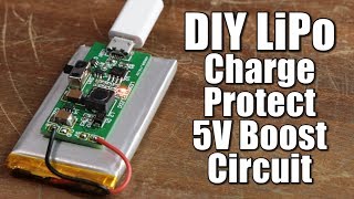
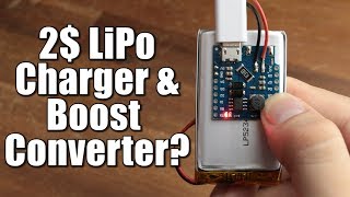
🔥I always use a 3.7V battery charger module and then I add a boost converter to get the 5V for my Arduino and so on. I wanted to have everything on the same PCB so I've used the protection ICs, charging and boost ICs and like that I have all I want on the same PCB. Hope you like it.
ELECTRONOOBS.io: electronoobs.io
Help my projects on Patreon : / electronoobs
my Q&A page: electronoobs.io/forum/index.php
Facebook page: / electronoobs
Canal en Español: / electronoobs en español
🔀LINKS
-------------------------------------
Tutorial page:electronoobs.com/eng_circuito...
Schematic: electronoobs.com/eng_circuito...
GERBERs(V1.0) free: electronoobs.com/eng_circuito...
Part list: electronoobs.com/eng_circuito...
Buy New Version(V2.1): electronoobs.io/shop/index.ph...
Fixed 5V or 12V output (V3.0): electronoobs.io/shop/index.ph...
📺VIDEOS
-------------------------------------
Magic 8 Ball: • Digital Magic 8 Ball -...
6 in 1 meter: • Homemade Distance, Ang...
GPS distance meter: • GPS distance and altit...
Arduino radio controller: • 3D printed Radio Contr...
Arduino multimeter: • Arduino based multimet...
🔬PRINTERS FDM
-------------------------------------
All printers: bit.ly/2lPkaS7
Artillery Sidewinderr X1 (333€): bit.ly/3fRcLbX
→ Coupon (324€) "D4FF9E1BE8227001"
Artillery GENIUS (245€): bit.ly/3hz9GNY
→ Coupon (241€) "H4FF9DA22F227000"
Creality3D Ender 3 (178€): bit.ly/2WOzQEw
→ Coupon (157€) "F4FE9A937B5EB000"
Creality Ender 3 Pro (220€): bit.ly/32QIjuH
→ Coupon (157€) "J4FE99F73D5EB001"
Alfawise U30 (181€): bit.ly/2BqrZ8O
Alfawise U20 (260€): bit.ly/3jxUG4V
Alfawise U50 (190€): bit.ly/2Br215b
Crealitu CR10 (345€): www.banggood.com/custlink/mvK...
Creality CR20 (363€): www.banggood.com/custlink/KvD...
TEVO Tarantula Pro (192€): bit.ly/3jErZn8
Anycubic MEGA- S (307€): bit.ly/30CP3tA
🔅PRINTERS RESIN
-------------------------------------
Anycubic Photon SLA (309€): www.banggood.com/custlink/mKD...
Alfawise W10 SLA (184€): bit.ly/30ABjPS
Longer Orange 10 (166€): bit.ly/2mkgCaN
Elegoo Mars SLA (210€): bit.ly/3hvk0GT
Like share and subscribe to motivate me. Thank you
#PCB
#charger
#boost - Věda a technologie


Sign up at ELECTRONOOBS.io: electronoobs.io/
Follow me on FACEBOOK for more: facebook.com/Electronoobs
help me on Patreon: www.patreon.com/ELECTRONOOBS
make a video on diy oscilloscope
Sir can you describe the design of digital volume controller and can we make a digital variable resistor. 🤔🤔
I know you did esc videos and have better things to do but could you make a 10s vesc for two bldc motors? I can't find anything that is in my budget range.
My first youtube video. It is about arduino LED Light Patterns
czcams.com/video/H7xZ_KfWxwY/video.html
Can this module at same time recharge battery and load something, somewere read that tp4056 need pmosfet to do that?
12:04 To fix this issue just connect the 20K resistor permanently to the circuit. Then, just calculate which resistor value you need to put in parallel to that to make 7K, and just make the switch connect it in parallel. That way, you can either have 20K or 20K in parallel with whatever is connected to the switch. This means you'll never have a floating pin.
Thank you so much for the tip
@@ELECTRONOOBS is this implemented in your version 2 of the gerber file or do we need to edit it?
A different solution would be switching the resistor to ground. In that way the ic will stop working while floating and turn on when the switch is closed again. Second feature is a damaged switch shut the ic down.
@@Aykaramber Switching the resistor to ground will mean that you could have the full output voltage (12v) on the feedback input, which may or may not be rated for it. So the best solution is to follow the datasheet and just connect a parallel resistor.
hi the parallel resistor is approx 12k
Your channel really has become a wonderful source for electronics projects and building instructions for "finished parts" like this one. Thank you!
Very helpful! I like how this video is released just at perfect time as I'm trying to design & make a lipo battery charger and boost converter for my project. This helps speed things a lot in that regard.
Great timing. This schematic is exactly what I need to build for a project I’m working on!
I made a similar PCB design for my final project degree a month ago. But the boost converter was fixed at 12v. Good to know it works
FANTASTIC. I've wished for such a circuit many times, to incorporate into my other PCB designs. I was too intimidated to try making my own so instead end up making headers on my PCB and piggybacking multiple modules. Since you did such an amazing job explaining this, maybe I can try to replicate it next time :-)
Nice integration of the 2 boards! Good job on testing too. Thanks for sharing!
Perfect - just what I've been looking for. Thanks for your work and clear explanation.
so much work delivered in 15mins, great content. thanks a lot
Great work! What a great way to make sure your prototype is working!
This was a really good video. Thanks for doing what you do! Still learning here and there is a lot of content to soak up here.
This is a great little power management board. Great work!!!
I ordered some PCBs of the newer version. The components just came in. I can't believe you hand soldered this, the components are way smaller than they look in the video!
I was looking for something like this for about 2 years =)) ,glad I subscribed to your channel.
Nice project man, you did a great job with this module.
BTW for the switching problem I don't know if someone has mentioned it or not but if you take a look into the Vout equation you can see that when you disconnect the resistor R1 for a very short time this makes its value approaching infinity and according to the equation the boost converter will try to reach a very large voltage value that will destroy the ic
I think the solution is to make R1 constant and change R2 according to the desired output voltage, this will make the switching moment voltage equals to Vref
Also, be aware of the current rating on the surface mount switches. Good engineering design calls for at least 2x margin, i.e. if the battery can sustain ~500 mA the switch needs to handle *at least* 1000 mA. (This margin should be much higher than 2x if we were dealing with higher power.)
One solution is to use an N-channel mosfet to switch ground back to the battery. Then attach the smd switch to the gate to turn the mosfet on and off. But when it comes to things like power supply, I don't like low-side switching as it leaves the load energized, so if it finds a ground it might turn itself on.
So if you can find a p-channel mosfet that handles the required current and can be saturated at zero volts (rather than having to go negative) you can switch the high side of the battery instead. So look for a P-channel mosfet whose Vgs(th) is only about half of the voltage you want to switch. This increases the likelihood of the mosfet going into saturation.
Nice video!! Your channel is growing awesome and your videos are so good now!
Nice circuit. I normally take the circuit out of a £1 powerbank for the 5v, protection and charging, but the 12v feature is nice.
I've been working with a power bank circuit but didn't notice it had an auto-turn off function built-in 🤦♂️, this circuit solves that problem right away
Awesom my friends for your all projects, from indonesia 🙏🏻 thaksfull
your project are always awesome, love from Nepal!
Great content, and a nice detailed explanation of the design process 👏. May suggest in theory that the booster short circuit could be fixed by a mosfet/pjt of the same rated current, as such, if the 5-12V switch at bounce state, the gate(mosfet) or base won't be supplied thus short circuit; you can ensure the drainage by a load resistance. Another way can be a capacitor put across the booster output so it doesn't lose current instantaneously at the switching action, however, this may be not the safest option to turn off in safe fail mode.
Thanks bro you r awesome. Real great content, learned a lot. Hope you do more projects like this.
Its awesome. Love your projects.
I struggled a lot for my battery management part.. but I was newbie than.. This looks perfect all in one solution.. copying your gerbers for future use.. thank you..
Awesome man.
REQUEST: you should make a pcb tutorial with easy eda. Like ground planes, etc. Best tips and tricks.
Thank You!
Hey Electronoobs, loving your video and concept for a charger/boost converter. I've recently made my own usb charger boost circuit and found that another IC made by TP to be even more suitable. The TP5400 comes as an all in one IC that can handle charge, boost, protect, and has internal mosfets. Might be worth taking a look at that IC. However, the only downside is that the datasheet is in Chinese only.
Better than a switch I think a jumper that you can just solder will be more useful to select the 12V: then the freed space you may use it to include a M2 hole in the pcb for fixing ir in the project case.
Regarding the output voltage selector switch: Why not simply put the 7.5k resitor in series with a 12.5k resistor and use the switch to bridge (short circuit) the 12.5k?
Nice video ! Excellent work.
Love your work! it would have been great if you would have added both 5 and 12v available simultaneously
that's awesome man...keep it up😍👌👌
Muy bueno. Te propongo otro con las mismas salidas pero con entrada de placa solar de 12v que suelen llegar a 17-19 voltios pico.
Excellent Work 👍
the pound land power banks have what you made already on them!! but making your own is far more gratifying, very cool video & they look class too...
Love ur commitment bro 💯👊👊👊
Cool board, but i guess i have a better solution to your problem. I suggest connecting the 20k ohm resistor (R1) permanently to the voltage divider so you would have 12V output and connect another resistor through a switch in parallel to the 20k resistor to obtain 5 volts output. This way the boost IC will always have its feedback loop closed.
Yeah
can you tell me the voltage of capacitor and wattage of resistor
@@jagdeepsharma1772 which capacitor and resistor?
Makes sense to me...I am also wondering about the lack of a big 100 uF buffer capacitor on the boost input side to handle startup surge current when the boost section is switched on....or maybe the MT3608 has soft start capabilities ?
is there quided video about this procedure? Idont have knowledge about electronics, but I have done projects by following youtubevideos
nice work,
I would've used a power management IC and a UC instead of all that, but I like how simple your design process is.
Which power management IC & UC specifically? please.
For small project that need 5v power i will just use a small powerbank module that have protection.
Like the 134N3P module that even smaller than the TP4056 but have 5v 1A boost, 4.2V overcharge, 3.0V overdischarge, and short circuit + over current protection
Impressive work bro
whats the total cost: if I was to order the V2 board 5 count assembled. it's hard to know the actual cost per board (fully assembled) without the required files ( before purchasing them) thanks
The booster IC blew because it had no voltage feedback and went overvoltage on the output.
As you flick the switch the IC momentarily loses voltage feedback and thus thinks that the voltage is too low and during that time the voltage rises to a level where the IC burns out.
So it's just a bad design on your part. :)
To fix this you could have left R1 permanently connected and had the switch connect a 12.3 Ohm resistor in parallel, which would lower the total resistance to 7.5k.
Or you could flip the thing around and place two resistors instead of R6 and one resistor instead of R8 and R1.
This way the regulator would jump down to 2.5V during the time it takes for the switch to make contact. This would also be the ideal way to do this because it would mean that in the event that the switch failed your regulator would not go overvoltage and burn out everything on the circuit.
Also your boost output capacitor should be placed as close as possible to the diode to minimize voltage ripple at higher current.
This is great, can this circuit be ordered completely built? I never soldered smd components, I also only have a normal soldering iron, I don't know if it's possible to do it myself.
Super Explanation..Thanks Bro
felicidades es un gran producto, vale cada centavo.
By the way, to make the board even smaller you could use a battery protection IC with integrated mosfet instead of the DW01. Check out this one: XB3303A. It's available in LCSC.
You are great
My greetings from Egypt
Very Good Job Man!!
good work freind, hello from Kazakhstan ))
Hi, great video. I learn a lot from this. Thank you.
What i am thinking right now is how charging state, full charge state, and battery fuel gauge also included so it can be monitored by arduino.
My prayers have been answered!
I found a similar module with a 9V/12V switch. The switch would break before make, so the boost IC burned when I switched the output voltage while powered, just like yours.
Maybe you should consider a make before break switch, or a different resistor configuration as suggested in another post.
A make before break switch would have avoided the problem.
Dear Electronoobs,
for the sake of the clearity i'd highly recommend cleaning PCBs with acetone before shooting. It makes them look much more professional.
:D
To solve your problem with boost ic, you can just add new two resistors in range 300k to 600k in Parallel to your old resistors and switch, so in normal operation the small value"old resistors" will take the controller and set the correct output, and when switch flipped the new resistors will kick in and set the output voltage to 5 voltage until switch flipped, after that the olde resistors will kick in and set the output voltage to 5V or 12V.
Excelente placa, yo diseñé algo con el tp4056 y el dw, pero no logré que funcionara, siempre se cortaba jajajaja, tuve que deshabilitar la parte del DW, por otro lado se me haría interesante que tuviera 2 salidas independientes, una para 3.3v (o 5v) y una para 7.5v ( para manejar pequeños motores), crees que haya problema si modifico tu diseño para que de una sola celda, tomen energía 2 sistemas BOST?
Awesome video😬
Great and thorough run through!
I have a question:
You are using a battery lower than 4.2V, does it make any difference what voltage battery is used?
Eg. If I put a 4.2V or 3.7V lipo to charge? Is there something I need to change for this?
By changing the inductor to a larger value would this mean that I can charge at a higher rate?
Nice explanation, it did leave me with some questions. Why didn't you have a 7k5 resistor on the MT3608 ic and have a switch add 12k5 resistance to the circuit ? Wouldn't that save the components you added and avoid the current spike for the MT3608?
excelente video! muy completo!!!
Wow bro........thanks bro given this information....you are great bro......
Super impressive as usual! I could see this module used for countless devices, and I will most definitely be a customer if you're able to get them produced to sell. =]
You've got a ton of talent, thanks for putting out great content with it!
Hello, I already had a problem using the DW01, he just couldn't keep the output off permanently. It restarted whenever the cut-off voltage increased, as the battery stabilized. It was necessary to trick it with 2 diodes in series for voltage drop and also an electrolytic capacitor to prevent reclosing. The shear stress of the FS312 seems more stable to me, test it if possible!
Great work, a powerpath would have been handy too
Your awesome bro.. waiting for the news Gerber file
You could have avoided the issue with the undersized inductor by looking at the commercial boost PCB with MT3608. The Chinese usually use the smallest/cheapest possible part to get the job done, so if your coil is smaller than theirs, it is most likely too small.
Super project! Very good and smart PCB. Would buy it as a kit. or if the price is right as a ready-made.
Very nice project! :)
But why you didn't add the new version to the video?
Looks good, nice project all in one but do you know the converter efficiency of the booster please
Nice circuit
Better solution for voltage select is to switch the resistor value by bridging one resistor in one state and connect both in series in the other mode.
Means for example 7.5k in series with 12.5k for the 20k in 12v, with the 12.5k bridged by the switch for 5v, so 7.5k in 5v mode and 20k with 12.5k connected/not bridged for in 12v mode. At no time is the feedback disconnected and it becomes safe to switch even with battery in place.
Great video and PCB! Just wondering - instead of adding a second switch why not just use 8.5K for R9 and then use a single switch to short out a 12.5K resistor? That way there is never an open circuit in the voltage selector.
Thanks for the great video! Can i also ask you to recommend a good book for beginners to get into electronics?
Is there a service where you can give them the file and a parts list and have them send them out as a kit at a cheap price really is buy them assembled but I just assume they will be relatively expensive
Awesome sir👍👍👍
Hello. Looking to use your design. It’s perfect for my use.
Looking for advice of changing a few things
For a 2s configuration. 7.2-8.4v
Would have to use 9v/12v boost
What would need to be changed on the charge protection
Different chip/resistor value changes?
Boost converter portions.
Same chip for 24v
Do I change the resistors for the higher voltage coming in.
Any help on values and portions would be appreciated!
Finally got a 3d printer to do more of your projects.
Hey, couple years back you revieved soldering station YIHUA 995D it still performs well?
Hilarious Datasheets - TP4056 Edition: Yes, I always wanted a LED in my circuits that indicates greed! I wonder what substrate they used for that... Lard nitride maybe?
Well done!! Impressive work!
You can connect one of the two resistors bettween C7 and R7 point for protection of U4 and let the switch toggle bettween the another resistor in parallel to give you the exact boosted voltage and open connection
.
*Fixed resistor 20k between C7 and R7 ( new connection )
*NC open ( new adjustment )
*NO 7.5k = R fixed // R toggled
Bettwenn C7 and R7 ( same connection)
7.5k = 1/( (1/Rt) + (1/20k) )
R toggle = 12k
So either 20k or 20k//12k = 7.5k
No floating point
Hope that helps
Thanks for the tip. Great idea!
@@ELECTRONOOBS keep it up!!
I've been following you since 4 years and you helped alot during my engineering degree till graduation
You mentioned that the PCB is populated one sided because of future need to order them preassembled from JLCPCB ? How much would this PCB cost assembled with all the components ? I suppose you could also do hot air reflow soldering at home instead of soldering each SMD component by hand.
The lipo battery yuo have connected, already has protection circuit built in (except short circuit) it has OVC OVD OVC protection in small PCB connected in between battery terminals!
Awesome, do you have a link to order the completed board?
Depending on the accuracy of the multimeter 12.49v is better than 12.8v on lithium cells, I like it.
can you tell me how i can get the entire pcb with all components ? I purchased the gerbers from your site but didn't realize i would still need to order the components and solder them on. Is there any way I can get this fully assembled ? Or can you tell me if there is something else like this that I can buy ? I have a bunch of projects that use lion and lipo batteries and I have the same problem as you, in needing a few boards to charge and boost power. Any help you can provide would be greatly appreciated. Thanks.
Banana looks cool
It is clear. But I have an doubt, how did you find cutoff voltage. I am doing simulation for this. In simulation how can I find cutoff voltage?. Please clear my doubt.
Can you tell me the exact version of the dw01 using ??? Because you are using dw01a (acc to schematic) which has an auto-recovery feature then you are able to achieve that during over-discharge, only USB input will enable the system.
Amazing 👌🏼
I have a question, what happens if you have the power supply (micro usb) connected and you have a loud at the end. Will the LiPo Cell charge or discharge? And will the load get current or not if i do it that way?
Nice video keep on going pal. :)
Hola. Tengo dos superCap de 2.4V. Son tipo Li ion. Crees que esté cargador me sirva ? Y quiero conectarlos en paralelo... necesitaría dos de estos circuitos. Muchas gracias. Espero tu ayuda
Great video 👌!!!
Do you have video for your power supply 10:10??? Looks nice 👍
Could you do an update video for V3? How do you select the output voltage as I don't see 2 seperate files for materials
amigo tienes algun tutorial de como usar esa pagina donde creas las PCBs, saludos desde mexico, exitos!!
Although I am a bit late to this, this is exactly what I'm looking for, I don't need the 12v so how would one remove it from the schematic?
I need a 12V Battery protector (Overcharge/Discharge) and monitor with bluettoth to check the voltage and to warn me if the Battery is empty.
Do you have a finished project or video like this?
So i made battery back 7s configuration. To be charger PD charger but it can only charge at 20V. My battery input output supports up to 30V charge. So i need to make boost converter that can turn my 20V to 30. Also disconnect it self from battery when battery is full. So that i can get max 30V out from the type c when i remove charger. It also needs to disconnect 30v from battery to type c, when ever charging is started.
Awesome. How can I make the same circuit to pull out to 5 amps?
Good job 👍 Thanks
I'm new to this. Does the download file contain list of components that need to be soldered into the pcb?
Do you have DIY from 12v to 5v with battery? I need for a nextion display on my car to use like a remote about 10-20min