When you thought that you had seen the best video and then stumble upon a video that not only explain what you wanted to know but also questions you newer knew existed! Thanks for sharing:-)
Really nice deep-dive in to crystals oscillators. Sure wish you'd make more videos because everyone is really informative and insightful. Thank You So Much!
Wow. I've been using this exact configuration for crystal oscillators for decades without ever really understanding it, & this is the first explanation I've ever seen that's ever made sense to me. Thank you so much!
both you guys are great. btw, when you are talking about phase shift, you are not referring to current versus voltage? i'm still trying to wrap my head around all the details :)
I loved this video! I'm very much a beginner and the relaxed yet informative presentation style was pitched exactly right. I'm subscribed and will be watching more of your videos. Might even have a go at building one.
Great job! Only clarification I would add is official def. of "Q" From wiki:: " the quality factor or Q factor is a dimensionless parameter that describes how underdamped an oscillator or resonator is, and characterizes a resonator's bandwidth relative to its center frequency."
This is an outstanding presentation. Thanks for taking the time to put it together. I’m a recently retired EE. While working I was focused on sonar systems and DSP (with almost no hardware design). Now that I’m retired I’ve decided to spend some time learning to lay out printed circuit boards using the Eagle PCB package. I’m also interested in exploring low power fm radio links for data telemetry. To cut to the quick, the circuit you presented seems like a fun one to try building with Eagle. As this would be my first ever pcb layout, I’m wondering if you can point me to reference materials that would help guide me in the layout of your circuit. Note that I’m not looking for an existing pcb realization of your circuit, only design guideline reference material. Thanks again and please keep producing great videos. - Best regards - Jim
Hi, I'm finishing university right now. As my master's thesis I've chosen to make my custom air sonar system. Could we talk together a bit, I think you'll be able to answer many if mine questions.
@hubercats I’m sure you’re got your question answered by now but there is software out there like KiCAD and Altium that help you design and condense your PCBs. I’ve also heard of JLBPCB but I haven’t heard any reviews from people. I’m almost done with my bachelors degree in EE right now. If either of you guys want to stay in constant that would be awesome. Although I may not have as much experience as you guys, I am very passionate about electronic design and am currently working with a small start up building circuits.
This video is so Fn Awesome, Thanks a lot. VERY VERY HELPFUL... Can watch this stuff all day long. Easy to understand and follow and the tool is damn good idea.
Hi devttys0,😃 Many Thanks for your great effort to make this kind of Tech video..👍 Now we can refresh our Technical skils from what you explain all tech matter with simple & efficient.👌 As you say "Analog Circuits" more fun compare to Digital.
One comment I'd have is that building the amplifier part of the oscillator doesn't necessarily have to be done with a BJT as presented here. You could just plop down an op amp instead, or likely you'd already have the amplifier available as part of a front-end inside a larger IC, which just requires the crystal as a frequency reference (with load capacitors at either side). In those cases, I think your analysis would still follow, provided you could derive the gm of the op amp or integrated amplifier, and its input and output resistances, from the datasheet or with some simple lab measurements. The other thing I'd point out is that an extension of this type of circuit is a digital oscillator, common in microcontrollers and other digital ICs, which are usually based around the same analog front-end shown here, with the output followed by a digital inverter with tightly controlled Vih and Vil. This is one of the basic building blocks of an embedded RTC, which are usually based around 32 kHz crystals, and are present in just about every embedded device I've ever worked on. Either way, great video and great explanation. Really dug the parts about viewing the xtal as a tightly controlled filter, and ensuring the phase delay is 360° with the load caps. Never thought of these circuits in that way, but it makes perfect sense! Finally, one thing I'll add is that trying to measure the power through a xtal directly is a serious pain and requires a very good AC current probe with high gain, since the current into the xtal is usually quite small (µA's) with lower drive voltages (
In digital design, this kind of oscillator is nearly always driven by a spare inverter or nand gate with the inputs tied together (effectively a very high gain inverting amplifier, in analog terms) from a chip that is already being used for other purposes.
Hi, I purchased one of the Dionex ovens for my lab. Mine is in quite a bit worse shape than yours inside, but the controls and blower/heater work fine. Did you have an E1 error code when you got yours, indicating a leak in the basin? I know it has to do with the two small cables on the bottom left side, but the components that used to reside in the leak sensor are long corroded. They are glass-body components that look like diodes. If you know anything about that part of the circuit and how to eliminate the E1 error, please let me know. Thanks!
Great video tutorial!! What is the program you are using to compute the Q, gain, etc? That looks pretty slick, and then you find out your circuit has its one internal capacitances, and thus those specified load capacitors don't quite work as advertised. Solderless proto-boards do not work well for RF at all. Welcome to practical real world electrical engineering! I will be visiting your Analog Zoo! 73s KI7AQJ
Do you believe the dip in frequency that you recorded at 40 degC was a fluke, or is there some phenomenon that causes that? Maybe you recorded a 6 for a 9, i.e. 28.376.492.6?
Don Bindner You know, I didn't even notice that when I was recording. While crystal frequency-temperature curves are non-linear (see typical f-t response here: www.4timing.com/images/sctempcurve.gif), in this case it is most likely that I just jotted down the wrong number. I really should get a GPIB interface set up for my HP frequency counter to do automated frequency tracking and eliminate operator error! :)
can u give me the values of the components if i want to generate a frequency of 1.7 mhz. which i am planning to do is connect the output of the oscillator to piezo disc for humidifier
Funny, I used to work on Hitachi HPLC systems and we had column ovens, but I never thought of using one for crystal ckt stability etc. You use a description of the transistor frequency para that I either can't hear or understand. Are you referring to the max operating frequency?
Hi, tutorial was exactly what I've been looking for. Can you tell me how you set up your circuit calculator. I have some slightly different values to crunch, is it a downloadable simulator or your own creation?
+Tim Dickerson It's all just implemented in javascript, but it's nothing terribly special. It just automates the design equations mentioned in the video (also see the references listed in the blog post; link is in the video description).
nice tutorial! can you please tell me what kind of simulator did you used in simulating the circuit in addition to that, may i ask if it is possible to transmit frequency signal of the circuit you design under the soil who has a 60k ohms resistance thanks!
and sir can you suggest to me any kind of oscillator/circuit that will produce constant frequency over a long period of time example 75 days. thanks again wish you continue helping us by uploading more educational videos like this thanks lads
if the capacitor in parallel and offer a least impedance and how how does that able to produce gain since most signal will just get to the ground point
devdevttys0ttys0 In my young days I built oscillators with out crystal but your explanation of an oscillator relies entirely on a crystal; so how did it work without a crystal? Thanks.
10:30 how do you get phase shift greater than 90 ? The crystal should act as an inductive load in series with c2. Shouldn't it lower the phase shift ? Is there any reference that can help me understand this....
Great job, sir any video on designing RF transmitter receiver module circuit say of 433 MHz transmitter receiver module circuit diagram , specifically for RC circuit
9:57 the crystal in resonance is resistive and yet it causes a phase shift of 90 degrees? i must have learned something wrong because from what i learned it should be 0 degree.
My 4.9512 MHz Crystal datasheet has following data mentioned in it Shunt Capacitance C0, Drive Level ,Equivalent Series Resistance ESR Table Load Capacitance CL => Range 8pF - 32 pF I am trying to Calculate Parallel capacitors needs for 4.9512 MHz C = 2(CL - C_Stray - C_pin) What value should i consider from the range of CL ( 8 - 32 pF)
You probably need to take a closer look at the datasheet. The range of 8pF - 32pF is likely for the entire product line which that datasheet applies to. The manufacturer should have a break down in there of specific load capacitances for specific crystal frequencies (e.g., for crystals from 20-30MHz, use 8pF; for crystals from 10-20MHz, use 16pF; etc).
+pa011w6435 The first page of the DS1307 datasheet shows how it should be connected. It's often useful to have some real-world designs to look at as examples though, and there are plenty of projects that use the DS1307; you can find several of them here: hackaday.com/tag/ds1307/
So if I have a crystal in a metal case, and it says 12 MHz on its case, does it mean that it has some oscillator built in, and I just need to connect some voltage through it to produce that particular frequency?
I just have a question you said we need Vrms to calculate the power of crystal but how can we get Vrms ? I knew that Vrms for square wave = V *(1/sqr(2)) but i don't think it's used in our case.
+rvngizswt Draw only the crystal and the two capacitors going from either side of the crystal to ground. Since both capacitors are connected to the same point (ground), that means that those ends the capacitors are connected to each other; remove the ground symbol and connect the two capacitor ends. You now have two capacitors in series connected across the crystal.
Where did the 90 degree phase shift come from? At series resonance is not the phase shift across the crystal zero ( and 180 degrees for parallel resonance)?
At series resonance, the crystal is resistive. If there were no other reactances (motional, parasitic, or otherwise), then there would be no phase shift. But there is an external capacitive reactance, C2. This forms an RC network with the resistive crystal, and as with any RC network there will be an associated phase shift.
The implication is that RC2 must be well passed the low pass break frequency to ensure the phase shift is asymptotically close to the 90 degree phase shift. It seems the problem with using series resonance is it makes the oscillator frequency more dependent on the other passive components, as the crystal is oscillating with a reactive impedance around the resonant frequency.
That's true, but the reality is that a full 90 degree phase shift is not required. Even if the phase shift is, say, 60 degrees, it would not provide positive feedback and oscillate. 90 degrees is a "worst-case" scenario, and even then there would not be a total phase shift of 360 degrees through the loop. The most common oscillators (Pierce, Colpitts) operate the crystal at a parallel resonance. Those that are series resonant (e.g., Butler) typically rely on the fact that there is no (or very little) phase shift through the crystal when it is resistive at series resonance; these oscillators intentionally do not place reactive components across the crystal. You do have to be careful about parasitic reactances there though; this is an advantage of the Pierce configuration in that C1 and C2 are usually much larger than any parasitic capacitances and hence swamp out those parasitics. Frequency will vary as C1 or C2 are change though, so high-quality low-tempco capacitors are a must here.
Wow, all this time I thought the quartz crystal is the one which causes the oscillations but it's the amplifier which does the oscillation, never thought the quartz crystal is used as a filter.
If you want a stable, but variable, frequency, your best bet is to use something that is digitally controlled. Look into PLL and DDS chips (Analog Devices makes many good DDS chips).
The step response of a crystal will be to vibrate when a sudden DC voltage is initially applied, but the vibrations will die off very quickly; afterwards the crystal acts like a capacitor, as the two crystal electrodes are separated by a non-conducting material.
I'm not getting why when the oscillator is at resonant frequency (acting as a resistor) there is a 90 degree phase shift. their shouldn't be any, unless you are also considering C2 at the same time?
Correct, it's the combination of the crystal's resistance and C2 that cause the required phase shift. That is why the capacitors C1 and C2 are required for oscillation (although sometimes stray/parasitic capacitance is sufficient, so some circuits omit one or both of these physical capacitors).
That's not good enough. I'll be charitable and say you were hasty and unprepared when you did the whiteboard, and now are seeking to escape with a bit of waffle. The whiteboard clearly shows the phase effect of all components - the 2 external caps, the internal cap, the internal inductance and the internal resistance. It clearly states, and you said when you were reading out your own whiteboard notes, that the resistance causes a 90 degree phase shift and the remaining 90 degrees has to be made up from 3 capacitances and 1 inductance. This is rubbish. No resistance causes any phase shift, ever.
14:45 Where the hell we connect power supply, or signal (+) in all those circuits? I can not understand how the hell it is supposed to work without current flow.
The circuit shown at 14:45 is not a complete oscillator circuit, just a model. The two resistors represent the input and output impedances of the amplifier, simply to demonstrate the effects of these impedances on the quality of the crystal's stability. The amplifier itself could be one of many inverting amplifier configurations, such as an inverting logic gate, or a common emitter transistor amplifier. Power would be applied to the amplifier itself to provide gain throughout the circuit; where exactly the power is applied would of course depend on the specific amplifier chosen.
The xtal does not have 90° phase shift of it has purely resistive impedance. Even if it did, why wouldn't that apply to the physical resistor at the input? You said the left hand capacitor introduces 75° phase shift. That's fair. Not so it's resistor.
If you really want to use them all at one time, you'll need 60 oscillator circuits. OTOH, if you want to have 60 crystals and use only one at a time the you could have just one oscillator circuit but you'd need a switch (mechanical, diode, etc) to swap each crystal in and out. The Colpitts oscillator configuration is usually preferred for this, since one of the crystal is grounded and it makes switching a bit easier.
Would have been nice to see the design equations derived, rather than just stated. it's a bit like the difference between cookery and chemistry, the former is following a recipe, the latter is science. That maybe a little critical given the fact that these are very good engineering videos, but equations like --gmXc1Xc2 giving the negative resistance needs a bit of explanation.
Actually, you explain things quite nicely so please keep up the good work. Some of us would rather get the concepts explained, and figure out the math later. I appreciate the work you put into this!!


I was reading about this for 2 hours and you explained more in the first 90 seconds than I had accumulated so far.
LOL so true.
When you thought that you had seen the best video and then stumble upon a video that not only explain what you wanted to know but also questions you newer knew existed! Thanks for sharing:-)
Thank you! Of all the thousands of videos out there explaining the workings of oscillators, you absolutely nailed it!
Really nice deep-dive in to crystals oscillators. Sure wish you'd make more videos because everyone is really informative and insightful. Thank You So Much!
I had so much trouble understanding this from the dry literature but you managed to explain it so well. Awesome!
Great video. I have watched about 5 so far, and this is the first to make sense. Thank you.
Wow. I've been using this exact configuration for crystal oscillators for decades without ever really understanding it, & this is the first explanation I've ever seen that's ever made sense to me. Thank you so much!
This is a fabulous video. Pure gold. Not a single wasted moment. Thank you!!
Thank you! I've been trying to find answers all over and this really broke down what I needed.
You really found a way to explain it simply and clearly!
You bring the world to us. Thanks and hoping for more.
one of the best explanations so far, great job
Nice job!
***** Thanks!!
devttys0 ***** Two amazing educators in the same video, wow. Thanks for the amazing practical explanation devttys0!
both you guys are great. btw, when you are talking about phase shift, you are not referring to current versus voltage? i'm still trying to wrap my head around all the details :)
well if w2aew says nice then it should be really nice..
you both rock!
Excellent discussion and full of useful info.
I loved this video! I'm very much a beginner and the relaxed yet informative presentation style was pitched exactly right. I'm subscribed and will be watching more of your videos. Might even have a go at building one.
Best video explaining crystal oscillators i've seen so far
so comprehensive :O Came from other video just to click-through, ended up watching whole
Absolutely brilliant explanation you have done a incredible job of explaining this thanks.
This tutorial is very good, keep up the good work! Thx
One of the best explanations that I've seen. I would like to see your presentation on RF and Audio amps!
Your videos ale pure gold! Keep them going! Thanks from Poland
This was really good. Just what I needed to see after failing to make a crystal oscillate for an afternoon.
One of my favorite channels, shame you don't post new stuff that often ;(
Great job!
Only clarification I would add is official def. of "Q"
From wiki::
" the quality factor or Q factor is a dimensionless parameter that describes how underdamped an oscillator or resonator is, and characterizes a resonator's bandwidth relative to its center frequency."
Wow .. very descriptive, awesome component analysis! I enjoyed it!
+BlueMonster78 Thanks!
This was a really great video far above the low tier educational videos, I learnt so much thanks. Have liked and subscribed
It was a lot of work for you. Thank you.
Thanks. You've made it very clear to me.
Excellent tutorial, thanks.
This is an outstanding presentation. Thanks for taking the time to put it together. I’m a recently retired EE. While working I was focused on sonar systems and DSP (with almost no hardware design). Now that I’m retired I’ve decided to spend some time learning to lay out printed circuit boards using the Eagle PCB package. I’m also interested in exploring low power fm radio links for data telemetry. To cut to the quick, the circuit you presented seems like a fun one to try building with Eagle. As this would be my first ever pcb layout, I’m wondering if you can point me to reference materials that would help guide me in the layout of your circuit. Note that I’m not looking for an existing pcb realization of your circuit, only design guideline reference material. Thanks again and please keep producing great videos. - Best regards - Jim
Hi, I'm finishing university right now. As my master's thesis I've chosen to make my custom air sonar system. Could we talk together a bit, I think you'll be able to answer many if mine questions.
@hubercats I’m sure you’re got your question answered by now but there is software out there like KiCAD and Altium that help you design and condense your PCBs.
I’ve also heard of JLBPCB but I haven’t heard any reviews from people.
I’m almost done with my bachelors degree in EE right now. If either of you guys want to stay in constant that would be awesome.
Although I may not have as much experience as you guys, I am very passionate about electronic design and am currently working with a small start up building circuits.
@@Minecraftmigapiku yo did you get end up getting your masters? 💪
@@Random.PCB. still working on it but most parts are already working. Can't say much more publically before defense, but would love to stay in touch.
Just found an awesome channel today.
Excellent tutorial ! Many Thanks.
Brilliant! Thank you!
Great tutorial. I learned a lot. Thank you
Your video is very great, everything is clear, thanks !!
This video is so Fn Awesome, Thanks a lot. VERY VERY HELPFUL... Can watch this stuff all day long. Easy to understand and follow and the tool is damn good idea.
+Martin P Thanks! The tool is a bit simplistic, but hey, it's free. :P Stay tuned for a follow up video discussing oscillator simulation.
informative, learnt something new!
Hi devttys0,😃
Many Thanks for your great effort to make this kind of Tech video..👍
Now we can refresh our Technical skils from what you explain all tech matter with simple & efficient.👌
As you say "Analog Circuits" more fun compare to Digital.
Great video!
Learned *a lot*, thanks!
Thank you very much. This video is really helpful.
blowing my mind bro. Thanks for sharing the knowledge
Great tutorial!
Awesome video!!
great videos!
One comment I'd have is that building the amplifier part of the oscillator doesn't necessarily have to be done with a BJT as presented here. You could just plop down an op amp instead, or likely you'd already have the amplifier available as part of a front-end inside a larger IC, which just requires the crystal as a frequency reference (with load capacitors at either side). In those cases, I think your analysis would still follow, provided you could derive the gm of the op amp or integrated amplifier, and its input and output resistances, from the datasheet or with some simple lab measurements.
The other thing I'd point out is that an extension of this type of circuit is a digital oscillator, common in microcontrollers and other digital ICs, which are usually based around the same analog front-end shown here, with the output followed by a digital inverter with tightly controlled Vih and Vil. This is one of the basic building blocks of an embedded RTC, which are usually based around 32 kHz crystals, and are present in just about every embedded device I've ever worked on.
Either way, great video and great explanation. Really dug the parts about viewing the xtal as a tightly controlled filter, and ensuring the phase delay is 360° with the load caps. Never thought of these circuits in that way, but it makes perfect sense!
Finally, one thing I'll add is that trying to measure the power through a xtal directly is a serious pain and requires a very good AC current probe with high gain, since the current into the xtal is usually quite small (µA's) with lower drive voltages (
In digital design, this kind of oscillator is nearly always driven by a spare inverter or nand gate with the inputs tied together (effectively a very high gain inverting amplifier, in analog terms) from a chip that is already being used for other purposes.
excellent, thanks
I finnaly understand .. THANK YOUUUUUU
Hi, I purchased one of the Dionex ovens for my lab. Mine is in quite a bit worse shape than yours inside, but the controls and blower/heater work fine. Did you have an E1 error code when you got yours, indicating a leak in the basin? I know it has to do with the two small cables on the bottom left side, but the components that used to reside in the leak sensor are long corroded. They are glass-body components that look like diodes. If you know anything about that part of the circuit and how to eliminate the E1 error, please let me know. Thanks!
Great v5de6!
Great video tutorial!! What is the program you are using to compute the Q, gain, etc? That looks pretty slick, and then you find out your circuit has its one internal capacitances, and thus those specified load capacitors don't quite work as advertised. Solderless proto-boards do not work well for RF at all. Welcome to practical real world electrical engineering! I will be visiting your Analog Zoo! 73s KI7AQJ
You are AWSOME!
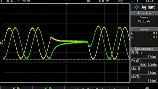
Do you believe the dip in frequency that you recorded at 40 degC was a fluke, or is there some phenomenon that causes that? Maybe you recorded a 6 for a 9, i.e. 28.376.492.6?
Don Bindner You know, I didn't even notice that when I was recording. While crystal frequency-temperature curves are non-linear (see typical f-t response here: www.4timing.com/images/sctempcurve.gif), in this case it is most likely that I just jotted down the wrong number.
I really should get a GPIB interface set up for my HP frequency counter to do automated frequency tracking and eliminate operator error! :)
can u give me the values of the components if i want to generate a frequency of 1.7 mhz. which i am planning to do is connect the output of the oscillator to piezo disc for humidifier
Holy C@#$! Where did the last 40 min go!!! Great Instruction!!
Funny, I used to work on Hitachi HPLC systems and we had column ovens, but I never thought of using one for crystal ckt stability etc.
You use a description of the transistor frequency para that I either can't hear or understand. Are you referring to the max operating frequency?
never mind :) i found it in the Fairchild data sheet it is the Gain BW product 300 MHz www.fairchildsemi.com/datasheets/2N/2N3904.pdf
Hi, tutorial was exactly what I've been looking for. Can you tell me how you set up your circuit calculator. I have some slightly different values to crunch, is it a downloadable simulator or your own creation?
+Tim Dickerson It's all just implemented in javascript, but it's nothing terribly special. It just automates the design equations mentioned in the video (also see the references listed in the blog post; link is in the video description).
Nice Job, but I have a request, may I know which software you used for getting load capacitance correct.
nice tutorial!
can you please tell me what kind of simulator did you used in simulating the circuit
in addition to that, may i ask if it is possible to transmit frequency signal of the circuit you design under the soil who has a 60k ohms resistance thanks!
and sir can you suggest to me any kind of oscillator/circuit that will produce constant frequency over a long period of time example 75 days.
thanks again wish you continue helping us by uploading more educational videos like this
thanks lads
thanks!
Did you move your blog to a new URL?
Is there any difference in quartz crystal that is cut from stone or melted down and formed?
George Pierce may be a relative of mine. Studying this is pretty surreal.
if the capacitor in parallel and offer a least impedance and how how does that able to produce gain since most signal will just get to the ground point
Hi, How to find out gm of not gate (SN74LVC1GX04). Is it going to be (Gain-1)/Rf ?
It would be interesting to know the frequency change when the supply voltage changes.
devdevttys0ttys0
In my young days I built oscillators with out crystal but your explanation of an oscillator relies entirely on a crystal; so how did it work without a crystal? Thanks.
4:58 what happen when you cut half the crystal and place is back will it give Double the frequency by physically changing the resonance??
10:30 how do you get phase shift greater than 90 ? The crystal should act as an inductive load in series with c2. Shouldn't it lower the phase shift ? Is there any reference that can help me understand this....
Very nice video! Thanks for interesting information.
Great!!!!
Great job, sir any video on designing RF transmitter receiver module circuit say of 433 MHz transmitter receiver module circuit diagram , specifically for RC circuit
9:57 the crystal in resonance is resistive and yet it causes a phase shift of 90 degrees? i must have learned something wrong because from what i learned it should be 0 degree.
My 4.9512 MHz Crystal datasheet has following data mentioned in it
Shunt Capacitance C0, Drive Level ,Equivalent Series Resistance ESR Table
Load Capacitance CL => Range 8pF - 32 pF
I am trying to Calculate Parallel capacitors needs for 4.9512 MHz
C = 2(CL - C_Stray - C_pin)
What value should i consider from the range of CL ( 8 - 32 pF)
You probably need to take a closer look at the datasheet. The range of 8pF - 32pF is likely for the entire product line which that datasheet applies to. The manufacturer should have a break down in there of specific load capacitances for specific crystal frequencies (e.g., for crystals from 20-30MHz, use 8pF; for crystals from 10-20MHz, use 16pF; etc).
What can be used as the amplifier?
VV helpful. But what I cannot find anywhere is how an oscillator interfaces with other circuitry - say DS1307 RTC.
Any suggestions??
+pa011w6435 The first page of the DS1307 datasheet shows how it should be connected. It's often useful to have some real-world designs to look at as examples though, and there are plenty of projects that use the DS1307; you can find several of them here: hackaday.com/tag/ds1307/
So if I have a crystal in a metal case, and it says 12 MHz on its case, does it mean that it has some oscillator built in, and I just need to connect some voltage through it to produce that particular frequency?
I just have a question you said we need Vrms to calculate the power of crystal but how can we get Vrms ?
I knew that Vrms for square wave = V *(1/sqr(2)) but i don't think it's used in our case.
could you share your circuit calculator?
great
Great 👍🏻👍🏻👍🏻👍🏻👍🏻👍🏻
can you help please me design a 7.77Mhz frequency oscillator?
For the gain margin formula, does that mean the gain is proportional to Ic? Because gm=Ic/Vt
can u tell me what is name of program is used in this video to design the pierce
Trying to understand, but which node of the cystal does the current exit? Also, how are those two capacitors seen as series to the crystal? Thank you.
+rvngizswt Draw only the crystal and the two capacitors going from either side of the crystal to ground. Since both capacitors are connected to the same point (ground), that means that those ends the capacitors are connected to each other; remove the ground symbol and connect the two capacitor ends. You now have two capacitors in series connected across the crystal.
+devttys0 Ah that makes sense, thank you!
Where did the 90 degree phase shift come from? At series resonance is not the phase shift across the crystal zero ( and 180 degrees for parallel resonance)?
At series resonance, the crystal is resistive. If there were no other reactances (motional, parasitic, or otherwise), then there would be no phase shift. But there is an external capacitive reactance, C2. This forms an RC network with the resistive crystal, and as with any RC network there will be an associated phase shift.
The implication is that RC2 must be well passed the low pass break frequency to ensure the phase shift is asymptotically close to the 90 degree phase shift. It seems the problem with using series resonance is it makes the oscillator frequency more dependent on the other passive components, as the crystal is oscillating with a reactive impedance around the resonant frequency.
That's true, but the reality is that a full 90 degree phase shift is not required. Even if the phase shift is, say, 60 degrees, it would not provide positive feedback and oscillate. 90 degrees is a "worst-case" scenario, and even then there would not be a total phase shift of 360 degrees through the loop.
The most common oscillators (Pierce, Colpitts) operate the crystal at a parallel resonance. Those that are series resonant (e.g., Butler) typically rely on the fact that there is no (or very little) phase shift through the crystal when it is resistive at series resonance; these oscillators intentionally do not place reactive components across the crystal. You do have to be careful about parasitic reactances there though; this is an advantage of the Pierce configuration in that C1 and C2 are usually much larger than any parasitic capacitances and hence swamp out those parasitics. Frequency will vary as C1 or C2 are change though, so high-quality low-tempco capacitors are a must here.
did you designed the simulation yourself? or can i download it from somewhere? please respond. thank you
Same requirement
Wow, all this time I thought the quartz crystal is the one which causes the oscillations but it's the amplifier which does the oscillation, never thought the quartz crystal is used as a filter.
If crystal is set as filter and not doing job of oscillator than how crystal as a Filter gives harmonic ?
would it be poss to transmitt over a full 1 MHZ ??? rather than one small simple frequencey
If you want a stable, but variable, frequency, your best bet is to use something that is digitally controlled. Look into PLL and DDS chips (Analog Devices makes many good DDS chips).
A varactor diode circuit should be able to pull the freq up and down some.
does the crystal always have to vibrate? or could i just apply a dc voltage and have it expand or contract when ever want?
The step response of a crystal will be to vibrate when a sudden DC voltage is initially applied, but the vibrations will die off very quickly; afterwards the crystal acts like a capacitor, as the two crystal electrodes are separated by a non-conducting material.
What is the frequency range?
shame the website is down
I'm not getting why when the oscillator is at resonant frequency (acting as a resistor) there is a 90 degree phase shift. their shouldn't be any, unless you are also considering C2 at the same time?
Correct, it's the combination of the crystal's resistance and C2 that cause the required phase shift. That is why the capacitors C1 and C2 are required for oscillation (although sometimes stray/parasitic capacitance is sufficient, so some circuits omit one or both of these physical capacitors).
devttys0 got it, thank you
That's not good enough. I'll be charitable and say you were hasty and unprepared when you did the whiteboard, and now are seeking to escape with a bit of waffle. The whiteboard clearly shows the phase effect of all components - the 2 external caps, the internal cap, the internal inductance and the internal resistance. It clearly states, and you said when you were reading out your own whiteboard notes, that the resistance causes a 90 degree phase shift and the remaining 90 degrees has to be made up from 3 capacitances and 1 inductance. This is rubbish. No resistance causes any phase shift, ever.
hey your blog domain expired. move to blogspot
14:45 Where the hell we connect power supply, or signal (+) in all those circuits? I can not understand how the hell it is supposed to work without current flow.
The circuit shown at 14:45 is not a complete oscillator circuit, just a model. The two resistors represent the input and output impedances of the amplifier, simply to demonstrate the effects of these impedances on the quality of the crystal's stability. The amplifier itself could be one of many inverting amplifier configurations, such as an inverting logic gate, or a common emitter transistor amplifier. Power would be applied to the amplifier itself to provide gain throughout the circuit; where exactly the power is applied would of course depend on the specific amplifier chosen.
The xtal does not have 90° phase shift of it has purely resistive impedance. Even if it did, why wouldn't that apply to the physical resistor at the input? You said the left hand capacitor introduces 75° phase shift. That's fair. Not so it's resistor.
Sir your website is not accessible!
and how or must i use about 60 diffrent crystals at one time ??
If you really want to use them all at one time, you'll need 60 oscillator circuits. OTOH, if you want to have 60 crystals and use only one at a time the you could have just one oscillator circuit but you'd need a switch (mechanical, diode, etc) to swap each crystal in and out. The Colpitts oscillator configuration is usually preferred for this, since one of the crystal is grounded and it makes switching a bit easier.
just 1 or 2 will do so how do i get a certin frequ on 27 mhz then
👍👍👍👍
You said that you were gonna square that wave, how??
Would have been nice to see the design equations derived, rather than just stated. it's a bit like the difference between cookery and chemistry, the former is following a recipe, the latter is science. That maybe a little critical given the fact that these are very good engineering videos, but equations like --gmXc1Xc2 giving the negative resistance needs a bit of explanation.
I go into much more detail on the math in my Colpitts Oscillator video, which derives the gmXc1Xc1 equation: czcams.com/video/I4bAfDu6F1k/video.html
Actually, you explain things quite nicely so please keep up the good work. Some of us would rather get the concepts explained, and figure out the math later. I appreciate the work you put into this!!