18 - Another RF Amplifier

Vložit
- čas přidán 1. 12. 2021
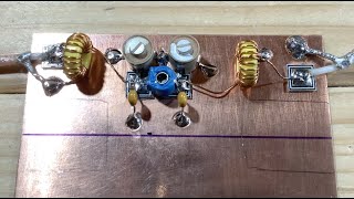
- Nick M0NTV builds and tests another small signal RF amplifier. This one is a simple one transistor design and comes from the hallowed pages of EMRFD (Experimental Methods in RF Design).
- Věda a technologie


Great video again, Nick and nicely paced. EMRFD is a wonderful piece of work and should grace every experimenter's bookshelf! 73 Martin G4FUI
Thanks Martin. Yes I keep going back to EMRFD and SSDRA and rereading bits. It's great when you think, "Wow, I actually understand that this time round!". 73 Nick
Great and informative video as always Nick, keep them coming, you-re teaching this ol' dog new tricks!
👍Thanks for sharing Nick. Some good info there. A formula that I use for converting peak to peak voltage to RMS power is Vpp squared divided 400. Only works for 50 Ohm load but saves on the calculations. E.g. if peak to peak voltage is 45V into a 50 Ohm load. 45 squared is 2025. 2025 divided by 400 is approximately 5 Watts.
Thanks Steve. That's a great little shortcut. I'll certainly remember that. Cheers! 73 Nick
Very detailed video, thanks for sharing. Althoguh there is a section dedicated exclusively to feedback amplifiers in EMRFD, section 2-something, that describes feedback amplifiers based on 2N3904. These amplifiers give a similar gain and consume only ~20 mA of current @ 13.8V. Other characteristics (noise figure, IMD, compression) are fine too. I used these amplifiers in several projects.
Thanks very much Alex. Yeah, I think 60mA is a bit much especially as I'm considering building another on the same board! Your suggestion gives me an idea though. Maybe what I should try is a smaller current design (like the one you mention) followed by a more beefy one like the one I built. I've usually only used those 2N3866 transistors in RF pre-drivers where I'm handling larger signals so it would probably go OK as the final amp in a chain perhaps. It's all good fun isn't it? Thanks again. 73 Nick
great again Nick merry Christmas can,t wait for the next one
Thanks very much William. 73 Nick
Thank you for great information, I was looking for this type of circuit for my QRP
Glad it was helpful. Thanks for watching. 73 Nick
Nice work. Thanks for sharing!
Thanks very much Andrew. 73 Nick
Fantastic video!!
Thanks so much Ed! Glad you enjoyed it. 73 Nick
Excellent video! regards from argentina!
Thank you very much Mauro! 73 Nick
I've found the cheap diamond hole saws from the likes of E-bay ideal for creating the islands when using the Manhattan construction technique.
ARRL HB of 1993 95 describes NFA or noiseless FB amplifiers also which are emitter to collector feedback amps with a ferrite transformer using a binocular core. Those have lower gains but are pretty good. Built a pushpull version several years ago
Sounds good. 73, Nick
When calculating the inductance of the transformer, do the bifiliar turns count as a single winding of 20 turns or do they interact to give a different result? Thanks.
Hi Graham! That's a very good question!!! I think because they are wired in phase that they would 'look' like a 20 turn inductor but to be honest I'd have to check that out for myself. The inductance is only significant here in as much as it produces the required impedance for the collector. When I was building mine I only looked at the impedance reading on the Peak LCR45. Mine was a bit low so I squeezed the turns together a bit more to get the desired result. Thank you for a great question though. I find transformers fascinating ... I know I should really get out more! 73 Nick
Great video! Can you please tell us what should we modify for the FM band in this circuit?
Hi there. Thanks. The circuit is really intended for HF. However, it is broadband in its design so you might be able to press it into service at higher frequencies but expect (1) lower gain and (2) the impedance match may not be as good. The 2N3866 transistor should be OK for the FM broadcast band though. An example circuit in the data sheet is for an amplifier at 400MHz- my.centralsemi.com/datasheets/2N3866_SERIES.PDF
So perhaps just it a go and see how you get on! 73, Nick
Excellent Nick! Would you please do a video on winding the transformer for this amplifier? D.K. KD6TK
Hi Don. OK - I'll put that on the list of future topics! 73 Nick
Cool beans,.
Like your bench. I built a similar bench and used a high gloss white oil paint to cover the sealed with shellac wood to make it easier to clean and easy to see the parts on the bench.
I am watching the video now, but as I watch I am asking myself can I feed the amplifier with any of my 5 watt QRP transceivers? It would be sweet if it could.
As I progressed I see it is not intended for inputting 5 watts. Should have known by the size of the transistor. But, it could be used as an amplifier for tiny transmitters to bring them up a bit.....
Thanks. Yes, it is a small signal RF amplifier so not suitable as a final power amp - unless you are very QRPppp! It could be pressed into service as a driver amp though but you'd need to give it some heat sinking. 73, Nick
Very nice!
Thank you very much! 73, Nick
You can build as many filters as you wish i will watch them all , it is very interresting
Your presentation is verry good thank you..
Thanks Bert. You're very kind! 73 Nick
Thanks a good subject!, although it looks simple, my experience is that these amplifiers are more a challange than you might think. For impedance matching to a xtal filter or mixer maybe a diplexer is a good subject for a next video.
Thanks Paul. 73 Nick
I have a question that lingers in my mind for quite sometimes....how do you multiple frequency and set it at 2.4Ghz or 2.8Ghz?
There are different ways of doing it I think. There are certainly designs I've seen for frequency doublers and triplers etc. Generating (stable) RF at higher frequencies is now easier than it used to be thanks to PLLs etc but I confess most of my work has so far been confined to below 50 MHz. An Si5351 will tackle these kind of frequencies easily. You'd need to contact some of the microwave guys - they'd be able to guide you. Thanks.
@@M0NTVHomebrewing from self experiment Ive used crystal oscillators at fix frequency of 125mhz
Muchas gracias por esa exelente explicación ,estoy atento a tus nuevos videos HK3DL Félix navidad para ti y tu familia
Hola Mario, muchas gracias por ver. Me alegro de que estés disfrutando de los vídeos. Mis mejores deseos para ti. 73 Nick
Nick recently tried a very similar design by EI9GQ from his Homebrew Cookbook and it was pulling 80mA, which is 1W input power and seems a little too beefy, but works very nicely indeed at 18MHz.
Thanks Steve. Yes, I got those 2N3866's from Graham but I've only used them in transmit drivers and pre-drivers before. I think I should have gone with thermal-pasting the can to the board though - it does get hot! 73 Nick
I just popped on a star heatsink and it seems fine. Also been playing with Pete's PSSST 2N2222 RF Amp, which seems quite good too.
@@M0NTVHomebrewing If you want to use the PCB as a heatsink for a "dead-bug" 2N3866 you could create a bigger island with your Dremel method. The EBC leads can then emerge without passing between IYKWIM.
Thanks Brian.
Nick can you tell me how the middle of a 200 ohm transfer is 50 ohms not 100 ohms what am I missing there? Throughly enjoyed the video thanks.
Hi Greg, my drawing was a copy of how EMRFD presented it but in truth its not the most intuitive way of doing it. I think it was done that way to emphasise the fact that it is an auto-transformer. Think of it like a voltage divider. The output is seeing half of the voltage from the collector (because of the centre tap). So if the output voltage is reduced by a factor of 2 then as impedance transformation is the voltage ratio squared - the output will see an impedance that is 2 squared (=4) times less than the collector. That's how 200Ω at the collector looks like 50Ω at the output. Hope this helps. 73, Nick
Nice Build. What coax cable connectors and coax are you using ?.
Thanks. In the video I just used some RG316 SMA patch leads to make temporary connections for testing. I did Pete Juliano's trick of buying a few and cutting them in half so one end is terminated in an SMA connector and the other can be hardwired to your board. When I came to using this amplifier in the actual radio it was hardwired with RG174 which is cheaper but more importantly more flexible. Hope this helps. 73, Nick
I prefer using glued down pads.
It's easier to remove a pad or put down another pad if you make a mistake.
You are right. Glued-down pads give you more flexibility. The engrave method is useful for things like edge-connected SMAs.
Hi
Going to build one to get a bit more out of a AD9850 based VFO which only gives about 250mVpp.
Question about winding toroid.
To make the centre tapped transformer.
Take a length of bifilar wire.
Solder one pair together - that's the centre tap for the output
Wind 10 turns onto the toroid.
The other two ends are used on the input side labeled G and R in the diagram?
Thanks Dave
Hi David! No - that won't work - you need to observe the phasing of the windings. That is indicated by the little dot on the schematic. This means that the centre tap is the bottom green connected to the top red. The easiest way is to get your bifilar wire, twist it in the vice then separate each end. Then wind your 10 turns on the toroid. Then make the centre tap (bottom green to top red). Then you can connect your top green to the 100n and 22Ω resistor and the bottom red to the collector of Q1. Please see this video on the actual construction of these kind of transformers (czcams.com/video/m4rOJNQg2y4/video.html).Hope this helps. 73 Nick
@@M0NTVHomebrewing Hi Nick Thanks for the advice yes Video 20 on the mixer clears up you to connect wiring to get the phasing correct.
I have some G-QRP Bifilar wire and some FT 37-43 toroids so will give it a go.
73
Dave
GM4NFI
No worries Dave. Happy winding! 73 Nick
60mA is quite high standing current for that device isn’t it? I guess it’s class A? Very interesting to watch as I’m working on (destroying) a bunch of these for a 4m driver. A friend donated them, which was very nice of him. I admit, I let a little bit of smoke out of one, amazingly it still works although the prognosis is probably not great for it🙄
Sir can I use this for wifi signal same as those expensive amplifier
Hi Danyal, the amplifier I built in the video was only designed to work at HF (and possibly lower VHF) frequencies. I certainly don't think it will cut it at the kind of frequencies you are talking about. The wavelengths are so tiny that lead lengths become critical and you require a whole different design. Sorry.
Can it be used with a Wi-Fi router with an antenna to increase the range of broadcasting?
Hi there! Although it is broadband I don't think it's THAT broadband. I think you'd need something built much more carefully for those kind of frequencies. Once you get in the GHz range then component lead lengths, stray capacitance etc. will play a bigger part as the wavelengths are so small at these frequencies. This amplifier is really for HF and probably lower VHF but I wouldn't want to promise anything higher. Hope this helps. 73 Nick
@@M0NTVHomebrewing thank you for everything
Can you do a video about your PCB technique (including making the pads, etc)?
Hi Henry! Thanks for the suggestion. I can certainly look at that. Meantime, if you are interested in the 'Dremmel' method that I often use then check out the other video I made on designing, building and testing an RF amplifier. But we can certainly revisit this whole subject again. Thanks. 73 Nick
You could try the diamond hole saws I mentioned up-thread. Readily available on that well known auction site.
@@boldford Thanks for the 411
Henry, if you're going to go down the route of more traditional Manhattan style with gluing on conductive pads (which I still do sometimes - although I prefer the Dremmel method these days) then you might want to investigate the 'Me Squares/pads' by Rex. Just google 'QRPme'. They are already tinned and you just break them off and stick them on. 73 Nick
@@M0NTVHomebrewing Good to know. Thanks. I'm breadboarding a circuit. It worked this afternoon but not now... Proves I am not Ben Eater... I used to do everything in Eagle and make one-off laser printed PCBs but it was more chemistry than electronics.
Hello Nick, Really good video - as usual. I'm lazy and calculate gain by 20xlog(180/33.6) though! Kevin M0XYM
Thanks Kevin. Nothing lazy about that. I just chose to do it the long way to show the connection between Peak to Peak voltage, RMS Voltage and Power. Thanks again. 73 Nick
Dear Nick Can you please explain about Ldmos AFT504, i want make the amplifier to boost some tools i must replace blt50 transistor with aft504 or make an amplifier after blt50
Tnx
EP2XX 73
Hi Kourosh, I'm afraid I'm not familiar with that device. All my power amplifiers have used regular MOSFETs. You should be able to find a few schematics online though. All the best in your building. 73 Nick
@@M0NTVHomebrewing if not problem please subscribe youtube CH if you not enjoy stay just for 1 month
Hi Nick, Great video and very interesting. As a newbie to the hobby (just passed my Foundation exam and waiting for a licence) I would also like to get into home-brew maybe an HF receiver (transceiver); are you planning to do anything like this that would suit people like myself just getting into the hobby? Have a fantastic Christmas and New Year, 73 Bob.
Hi Bob! Thanks very much. Congratulations on passing your Foundation exam! Very well done and welcome to the hobby. It was when I began studying for my Intermediate that I started to really get into the homebrew scene. There are some excellent resources around. I can't do better than recommend the tremendous work of Pete Juliano N6QW. My first SuperHet and HF transceiver borrowed heavily from his designs. Pete has a number of folk tackling his recent direct conversion receiver (a good one to start with). He has also recently published his designs and extensive build notes for a 20m transceiver that essentially uses just 7 transistors. It is called the PSSST-20. CZcams won't allow me to put a direct URL here but just google his callsign and you'll find him or send me a direct email and I'll hook you up. I will eventually get round to doing some video stuff around this area but for now I'd check out Pete's work. 73 Nick
@@M0NTVHomebrewing Couldn't agree more. And he cites your work on crystal filters too! Kevin M0XYM
Thank you for your reply, I have found Pete on CZcams and also his web site. So much looking forwards to getting into the hobby. Do please continue to keep putting out your very interesting videos, they are inspiring. 73 Bob
Sir I'm a hobbyist , want to know about the schematic used for RC toy cars etc . Want to know how the signals are transmitted from transmitter to receiver module's of the RC car to control the motor in toy car . Detail explanation of the circuit used in the transmitter and receiver how it works step by step . Sir any video on this topic , or any book or magazine have this kind of projects
Hi there. I'm afraid I don't have any experience in this field but just googling 'radio controlled cars diy' brings up a load of web pages and videos. You should find something to get you started. All the best, Nick.
Perfect
Thanks very much. 73 Nick
@@M0NTVHomebrewing 73 kourosh
Why not have square island RF breadboard pattern boards be made by pcbway etc and you can sell them too? Elektor had these type of boards some 30 years ago
Personally I prefer to either engrave or stick my own pads precisely where I need them. If you fill the whole board with separate electrically isolated squares then you lose the common ground plane effect which is one of the great benefits of Manhattan style construction. But each to their own! 73, Nick
The grid pattern had ground lines between squares. Also possible to have continuous ground plane on other side. drill hole and connect to ground plane. Grid was like 200 mil or 1/4 inch. I cant find pictures of it but these definitely existed and were sold for this RF breadboarding purpose. @@M0NTVHomebrewing
That would certainly help. 73, Nick
The more gain you apply the more you apply it not only for the signal but for the noise as well. It doesn’t seem like a good idea. I mean it seems gain+attenuation=more noise
Hi there! There is a balance between gain and attenuation that runs through a whole radio I would suggest. Sometimes it can be a fine balance i.e. just 1 dB too much gain has caused an amplifier to oscillate. Ultimately you have to decide what you want to settle for. Some gain upfront in a receiver can actually reduce the overall noise figure. It is a balancing act! Thanks for watching and commenting. 73, Nick
Nice video.
2N3866 well known device, but mainly used as a driver for a VHF PA! My very first rig a Trio TR2200 which was a 6 channel crystal controlled 2m box, used one as the PA, with a full charge it would produce a whole 1W output on 145Mhz.
Using something like the 2N3904 as has been suggested would be better.
Twisting the wire.. A clamp and twist? you do like hard work. Have you lost your old hand drill?
One end in vice, the other in drill chuck and a few turns of the handle and the jobs done. :-)
Or tie the ends together, slip in a screwdriver and spin that.
Keep the vids coming - there is nothing like a simple practical approach to actually learning about electronic construction.
Andy
Thanks Andy. The reason I chose this particular design from EMRFD with the 2N3866 is that the authors (Wes, Rick & Bob) say it is one of their favourite amplifiers for terminating a switching mixer. I figured with a recommendation like that it was at least worth building one! Thanks again. 73 Nick
looks around in room... niope no cherry 2000 here... hahhahaha good jbo oldman. do you have a radio scd ? iam in 2 land state side. phone only. 73
Here is a Naive question - why are there no multi-band (uhf/vhf) amplifiers? I see BTech having 3 different PAs for the 3 HT bands (2m, 1.25m and 70cm) but each is a separate unit.
Now, I am feeling like a customer asking the question, "why can't I just move the toilet to the other side of the bathroom?", I get it. But I have seen military-use portable multi-band amplifiers covering 50-500Mhz. So I know it's possible to make a compact unit - Why aren't companies making them?
Hi! No worries - there's no such thing as a naive question! When it comes to small signal amplifiers then there are plenty of low noise amplifiers on all the usual online platforms that cover DC to several GHz with up to 30dB gain. RF Power Amplifiers are a different matter. As I only really build my own gear I can't really comment on why commercial companies decide to make or not make certain things. All I can say is that from experience building RF power amps that are stable and relatively clean at above QRP power levels is not trivial. HF is bad enough but once you get higher in frequency then the real challenge comes in your ability to physically construct the thing so that it works the way you intend. Physical board layout, component lead lengths, stray capacitance etc. all start to become a much bigger deal as you go up in frequency. Basically it gets harder. But where would be the fun if it's easy? 73 Nick
Dear Friend Nik, good afternnon!!! Please, this book is your, the author!? I would like to buy one! How I do it!?
If you are referring to EMRFD (Experimental Methods in RF Design) then it is by Wes Hayward, Rick Campbell and Bob Larkin. It is now out of print again I think and can be quite expensive to buy. There are some PDF versions available on the internet or you may get lucky and find a second hand copy. It's a great resource. 73, Nick.
Full calculation show
I'd enjoy a build using a single russian mini vaccum tube pentode..
I've never dabbled with valves/tubes - I'm a solid state guy really. Each to their own though and maybe one day I will. 73
Great and informative video as always Nick, keep them coming, you-re teaching this ol' dog new tricks!
Thanks mate! High praise indeed - thank you for all your help and encouragement. See you soon. 73 Nick