Here are some additional tips people have found helpful when aligning FiberPorts: Pre-Alignment with FC/APC Connectors: When the fibers have FC/APC connectors, we recommend using the same procedure to pre-align both FiberPorts. The recommended procedure, which is shown during 4:44 - 8:57, is performed without another FiberPort mounted in the FiberBench. This avoids transmitting the beam through the opposite FiberPort during pre-alignment. The reason for this recommendation is that, if the fiber has an FC/APC connector and if the opposite FiberPort is attached, a properly aligned beam will be clipped as it travels through the opposite FiberPort. A clipped beam makes determining the proper alignment difficult. Choosing a Direction when Making the First Z-Axis Step During Fine Alignment: After completing the pre-alignment step, the free-space beams will be nearly collimated. The first time the lens cell position in either fiber port needs to be adjusted along the Z-axis, we recommend moving the lens farther from the fiber, by rotating the Z-Theta screws clockwise. The clockwise adjustment moves the beam waist towards a point half-way between the two FiberPorts for optical coupling. Visualizing Beam Overlap: During alignment, it can be helpful to input light simultaneously to both FiberPorts. When this is done, the overlap of the beams within the FiberBench can be seen.
@The Rojecas Yes, indeed! The red light you see is typically called leakage. Light leakage is not only common, it can also be a handy alignment tool when observed near the fiber connector. Leakage is common since it is almost impossible to perfectly couple all of the light from a light source into a single-mode fiber core. This is because perfect coupling into the core would require perfectly matching the size, shape, and alignment of the light’s beam waist to the optical fiber’s mode field diameter and geometry. Inevitably, the match will be slightly imperfect, and some light will be coupled into the fiber’s cladding. Because light coupled into the fiber’s cladding is not guided well, this light propagates out of the cladding and into the fiber’s surroundings. This is what makes the fiber’s yellow jacket glow red in the video. This phenomenon can be a useful alignment tool when working with visible light sources. When you start to see the fiber jacket glow near the connector, you know your light source is overlapping the fiber’s end face. As the alignment improves, more light couples into the fiber core and less light will leak into the jacket. Some people look for the leakage near the connector to dim to confirm their alignment.
Thanks for the video. I had already established a two way coupling efficiency of approx. 75% based on your manual a month ago using your fiberBench and fiberports. My suggestions would be that one need to be more careful with the beam collimation. If the beam is well collimated, it is much easier for coupling and you have to less adjust Zthetas.
We’re so happy to hear you developed an approach that works well for you! Thank you for sharing what you’ve learned. You are not alone in preferring to spend more time during the pre-alignment step to better optimize collimation. In fact, when using APC connectors, it is critical to perform the full pre-alignment step for both collimators. One reason for our demonstrating an alternate approach was to show alignment still concluding successfully if the collimation was not optimized during pre-alignment.
@JyotiArya-bw1lg The FiberPort includes a fiber collimating lens, so both collimate light from a fiber. However, the FiberPort is also a mount that includes a 5-axis micro-positioner and can be integrated into a FiberBench. A FiberPort’s additional functionality and stability can be useful when assembling and aligning setups.
We thought the video was already a bit long with a single configuration, so we obviously left out discussions about alternative connectors like FC/APC or bare fiber terminators ( www.thorlabs.com/newgrouppage9.cfm?objectgroup_id=8543 ). When using an FC/PC bare fiber terminator, the overall procedure should be the same as long as the ferrule was sized appropriately for the fiber and the fiber does not extend so far beyond the ferrule that the fiber droops from gravity. If you’re interested, we did demonstrate the use of a bare fiber terminator ( www.thorlabs.com/newgrouppage9.cfm?objectgroup_id=8543 ) in a different Video Insight. It is featured around 4:11 in "Cleave a Large-Diameter Silica Fiber Using a Hand-Held Scribe" (czcams.com/video/-2dGyrvYGrQ/video.html). Please let us know if there is any more detail would like to see with the bare fiber terminator.
9:58 Perhaps remind the user to turn off their source before swapping the cable? Always makes me nervous to move a fiber tip without verifying disabling of the output.
We agree it is a good practice to follow! In fact, we made a point of mentioning that we turned the laser source off before the swap (9:21). It was turned on again at 10:30.
I am trying to couple multimode fiber with Nd: YAG laser (532 nm) wavelength but the main problem is a limited output laser energy (up to 5 mJ) through the fiber (400 um core multi-mode). How can I increase coupling efficiency to achieve 20mJ output energy?
We're happy to help, but in order to provide assistance, we'll need more information about the setup. Please contact Thorlabs Tech Support at techsupport@thorlabs.com or give us a call ( www.thorlabs.com/locations.cfm ) to discuss your approach. We hope to hear from you!
We absolutely recommend wearing laser safety glasses as directed by your facility's laser safety guidelines. We chose not to wear glasses during this demonstration, since we ensured the laser power in the free space beam was ~1 mW prior to filming, which falls under the guidelines for a Class 2 laser. You can see us with safety glasses in our "Setting Up a TO Can Laser Diode" Video Insight ( czcams.com/video/YshMuSfIcBQ/video.html ).


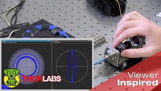


Here are some additional tips people have found helpful when aligning FiberPorts:
Pre-Alignment with FC/APC Connectors:
When the fibers have FC/APC connectors, we recommend using the same procedure to pre-align both FiberPorts. The recommended procedure, which is shown during 4:44 - 8:57, is performed without another FiberPort mounted in the FiberBench. This avoids transmitting the beam through the opposite FiberPort during pre-alignment. The reason for this recommendation is that, if the fiber has an FC/APC connector and if the opposite FiberPort is attached, a properly aligned beam will be clipped as it travels through the opposite FiberPort. A clipped beam makes determining the proper alignment difficult.
Choosing a Direction when Making the First Z-Axis Step During Fine Alignment:
After completing the pre-alignment step, the free-space beams will be nearly collimated. The first time the lens cell position in either fiber port needs to be adjusted along the Z-axis, we recommend moving the lens farther from the fiber, by rotating the Z-Theta screws clockwise. The clockwise adjustment moves the beam waist towards a point half-way between the two FiberPorts for optical coupling.
Visualizing Beam Overlap:
During alignment, it can be helpful to input light simultaneously to both FiberPorts. When this is done, the overlap of the beams within the FiberBench can be seen.
In the single mode fiber you can see that are light leaking the yellow jacket glow red.
@The Rojecas Yes, indeed! The red light you see is typically called leakage. Light leakage is not only common, it can also be a handy alignment tool when observed near the fiber connector.
Leakage is common since it is almost impossible to perfectly couple all of the light from a light source into a single-mode fiber core. This is because perfect coupling into the core would require perfectly matching the size, shape, and alignment of the light’s beam waist to the optical fiber’s mode field diameter and geometry. Inevitably, the match will be slightly imperfect, and some light will be coupled into the fiber’s cladding. Because light coupled into the fiber’s cladding is not guided well, this light propagates out of the cladding and into the fiber’s surroundings. This is what makes the fiber’s yellow jacket glow red in the video.
This phenomenon can be a useful alignment tool when working with visible light sources. When you start to see the fiber jacket glow near the connector, you know your light source is overlapping the fiber’s end face. As the alignment improves, more light couples into the fiber core and less light will leak into the jacket. Some people look for the leakage near the connector to dim to confirm their alignment.
Thanks for the video. I had already established a two way coupling efficiency of approx. 75% based on your manual a month ago using your fiberBench and fiberports. My suggestions would be that one need to be more careful with the beam collimation. If the beam is well collimated, it is much easier for coupling and you have to less adjust Zthetas.
We’re so happy to hear you developed an approach that works well for you! Thank you for sharing what you’ve learned.
You are not alone in preferring to spend more time during the pre-alignment step to better optimize collimation. In fact, when using APC connectors, it is critical to perform the full pre-alignment step for both collimators. One reason for our demonstrating an alternate approach was to show alignment still concluding successfully if the collimation was not optimized during pre-alignment.
What is the difference between Fiber port and Fiber collimator ? Do both of them collimate the beam ?
@JyotiArya-bw1lg The FiberPort includes a fiber collimating lens, so both collimate light from a fiber. However, the FiberPort is also a mount that includes a 5-axis micro-positioner and can be integrated into a FiberBench. A FiberPort’s additional functionality and stability can be useful when assembling and aligning setups.
Some tips regarding coupling the bare fibers with bare fiber terminators would have been great.
We thought the video was already a bit long with a single configuration, so we obviously left out discussions about alternative connectors like FC/APC or bare fiber terminators ( www.thorlabs.com/newgrouppage9.cfm?objectgroup_id=8543 ). When using an FC/PC bare fiber terminator, the overall procedure should be the same as long as the ferrule was sized appropriately for the fiber and the fiber does not extend so far beyond the ferrule that the fiber droops from gravity.
If you’re interested, we did demonstrate the use of a bare fiber terminator ( www.thorlabs.com/newgrouppage9.cfm?objectgroup_id=8543 ) in a different Video Insight. It is featured around 4:11 in "Cleave a Large-Diameter Silica Fiber Using a Hand-Held Scribe" (czcams.com/video/-2dGyrvYGrQ/video.html). Please let us know if there is any more detail would like to see with the bare fiber terminator.
@@thorlabs thank you for your comment. Much appreciated.
9:58 Perhaps remind the user to turn off their source before swapping the cable? Always makes me nervous to move a fiber tip without verifying disabling of the output.
We agree it is a good practice to follow! In fact, we made a point of mentioning that we turned the laser source off before the swap (9:21). It was turned on again at 10:30.
@@thorlabs Great safety practice!
thnks
I am trying to couple multimode fiber with Nd: YAG laser (532 nm) wavelength but the main problem is a limited output laser energy (up to 5 mJ) through the fiber (400 um core multi-mode). How can I increase coupling efficiency to achieve 20mJ output energy?
We're happy to help, but in order to provide assistance, we'll need more information about the setup. Please contact Thorlabs Tech Support at techsupport@thorlabs.com or give us a call ( www.thorlabs.com/locations.cfm ) to discuss your approach. We hope to hear from you!
Laser goggles !!?
We absolutely recommend wearing laser safety glasses as directed by your facility's laser safety guidelines. We chose not to wear glasses during this demonstration, since we ensured the laser power in the free space beam was ~1 mW prior to filming, which falls under the guidelines for a Class 2 laser. You can see us with safety glasses in our "Setting Up a TO Can Laser Diode" Video Insight ( czcams.com/video/YshMuSfIcBQ/video.html ).