Transistor as a switch - low side or high side

Vložit
- čas přidán 2. 07. 2024
- Transistor as a switch - low side or high side
www.pcbway.com/ Get 5 boards in about a week for $22!
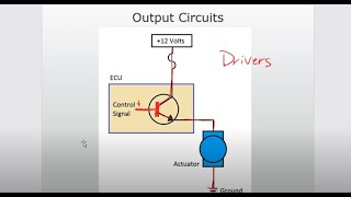
In this video we look at transistor as a switch. That means the transistor goes from fully off (cutoff) to fully on (saturation). As we look at this use of the transistor we look at where in the circuit relative to the load should we place the transistor. Before or after the load. Finally we look at using a BJT NPN to switch. an N channel MOSFET.
Yes!! I now have merch: teespring.com/stores/learnele... Electronics themed T-Shirts!
HEY YOU ABOUT TO POST SOMETHING STUPID:
Yes, I know my hands are large/fat. It's because of a heart condition I suffer from called Congestive Heart Failure. Here's a link to some information about CHF: cle.clinic/2TdS2Ux
One of the symptoms is that is causes fluid retention, mostly in the hands, feet/ankles, and face.
It will kill me one day. I'm doing ok right now, but someday...
--------------------------------------------------------------------------------------------------------------------
If you are shopping for electronic components, test gear or consumables please consider visiting my Amazon shop @ amazon.com/shop/learnelectronics
Please check out www.patreon.com/learnelectronics and pledge a dollar if you can. It will go a long way to keeping the channel alive. It costs a bit of money to buy all the items and produce these videos. You help is appreciated.
---------------------------------------------------------------------------------------------------------------------
Or....if you'd like to send a one-time donation you can use this link: paypal.me/learnelectronics
----------------------------------------------------------------------------------------------------------------------
Geaqr I use:
DMM: Owon B33+ - amzn.to/3qQgH20
Power Supply: Matrix 3206 - amzn.to/37C0fL9
Portable O'scope: YEAPOOK ADS1013D - amzn.to/2ZG4G3x
Bench O'Scope: Hantek DSO5072P - amzn.to/3pUl2jL
Soldering Station - KSGER T12 - amzn.to/2NuNdby
Multimeter leads: Probemaster - amzn.to/2ZJ0BLK - Věda a technologie


Why are you not using complementary transistors for high side switching? I would use an PNP transistor on the high side, to avoid the complication of a Vbe drop, by allowing the collector always to be connected to the load. A similar situation with enhancement mode mosfets, I would use a P channel mosfet. There are considerations of finding fets with the necessary speed or Ids current that may limit the choice, but in general the complimentary transistor is the first choice.
Personally, I like to use open collector ( open drain ) transistors for interfacing between circuit boards. This is because the one voltage which is not subject to voltage regulation tolerance is zero volts. The ground can have noise on it, but in general it is a well defined logic signal. For similar reasons, high side switching is a preference. It is possible to design circuits fail safe and to be tolerate to at least one fault. I try and design my circuits so that a simple fault will not let out the magic smoke and force a component replacement. One simple example is when driving an LED, it is always best to connect the current limit resistor to the supply rail and the LED in series to the load. The reason is that an accidental connection to ground by a scope probe will not destroy the current limit resistor, but would most likely instantly destroy an LED connected directly to the supply rail.
By using high side switching and open collector drives, it's possible to engineer the interface to survive a short to either rail. This is achieved, simply by dividing the drive circuit limit resistors into two separate resistors. One in the collector feeding the high side switch, and one in the base or gate bias to the high side switch. Both resistors limit the current and can usually survive a momentary short to rail, either because the current flow is limited or because the short is to their respective passive rail. (Nothing happens when an open collector is shorted to ground.)
Fault mode analysis is always worth doing on any new design, as minor changes in circuit topology can result in a circuit that is fault tolerant and thus far more reliable. During my time as an industrial circuit designer, I attended many circuit peer review meetings. In these, the designer was required to justify the inclusion of every component and explain why a particular value had been chosen. In some cases, this came down to the component being required, but it's value chosen simply to reduce the number of different values included on the bill of materials.
I wanted a brief into to what low/high side switching was all about and you , nailed it! Many thanks.
Very informative video. Thanks!
Brief and to the point. Thank you for sharing !
Thanks for this. For a future episode, perhaps investigate PNP Transistors and P-Channel MOSFETs for high side switching (and how a logic zero turns them on). For NPN and N-Channel - high side switching requires a voltage HIGHER than VCC to FULLY turn them on. For NPN transistors, it's about 0.6 volts higher and possibly several volts higher for N-Channel (depending on type and current).
For reference, you described Emitter-Follower (a.k.a. Common Collector) and Common Drain (a.k.a. Source-Follower) circuits. Again, the downside is you cannot switch fully to the positive rail with these circuits, therefore causing higher heat and a lower voltage than expected. The downside to PNP and P-Channel is they are typically less common and more expensive - although I don't think that was always the case. I remember pulling apart radios in the '60s that had positive ground and PNP transistors (yea, I'm old).
Not only old. You're savvy too. Two conditions that aren't always related!
Yeah, I'd definitely use pnp or p channel for high side switching. Way more efficient.
i was just watching a video about 20min's ago switching the load on the high side(collector side) or the low side(emitter side) but it was utilizing a MOSFET INSTEAD.. (an N channel one too.)
very well explained Paul.. You hit all the pit fall's one would come across using this circuit. WELL DONE! : )
great stuff thanks as always
Thanks. I’ve had issues with this topic. Very helpful.
Amazing, I had the question, you had the answer clear and concise! thanks!
Really useful info. You’d be surprised how often this comes up. Most new users always reach for a npn right away then try to switch an common cathode and wonder why it doesn’t work as expected. Likewise, for PNP. One of your best videos. Thank you
Glad it was helpful!
Great point about the current going to ground.
Useful to know, Cheers Paul.
I always use open collector for variable vcc swithcing, but I have never considered the ground v drop! Very good note I need to start considering
Great refresher!Thanks.
i realize I'm pretty randomly asking but do anybody know a good website to stream new series online ?
@Marcel Sincere I use flixzone. You can find it on google :)
@Marcel Sincere i watch on flixzone. You can find it on google :)
Thank you this is going to help me a lot
Very informative
Nice info, thanks :)
Thank you sir this helps a lot for a begginer like me
You should also consider using PNP BJT.
Helpful video
Did you say "switch-uation"? lmao good one Paul, you had me laughing with that one.
i was about to comment on that too haha
That;s what I heard too! Played it 3 time to make sure... :-)
LLAP
@@stuffandjunkanduhh5049 that's the first time I've heard that 😁
Cool video, thanks mate
Thanks 👍
Great topic for a video, sometimes I'm stumped on which to use as it's not always clear (at least to me lol)
Awsome vid bud.
I faced this situation some time ago when self-learning about transistors. My natural 'instinct' was to put the load on the emitter (high side). But it didn't give the behaviour I was expecting nor wanted. I put the load on the collector (low side) and hey presto, the transistor did exactly what I was hoping it to do.
I couldn't rationalise the difference. To try and understand why is it different, I read more on the NPN junction. After wading through people just repeating the usual bland 'base level' info about transistors (;)) I came across source of information (;)) that the NPN junction isn't actually symmetrical. That helped me understand there'd be a difference between high and low side configurations. Anyway, since that time I've always put loads on the collector (low side) and never had a problem since.
I suspect that if the load on the emitter line has too high of a resistance then the possibility exists where a back-current may force its way from the collector through the base! (diode breakdown scenario) which wouldn't end well I suspect.
So dropping voltage on the collector line entering the diode junction will reduce any chance of a back-current.
Thanks for all your videos.
Thanks.
Thank you
Excellent 👌👍👏
You didn't mention a huge part of using a high side switch which is your gate potential has to be a lot higher than your drain since the source voltage is no longer 0 volts.
Which is why it's easier to just use a pnp or p channel transistor.
Very interesting
would be nice to see more about driving MOSFET on high side
if it helps, still struggling conceptually decades after the forrest mims booklets, i've never conceived of low side switching. amazing. following + to perform tasks seems logical. hopefuly i'll understand other people more now.
thankz, now im already aware why pir sensor has high side switching
thanks
simplicity is the ultimate sophistication
Thanks, Elohim bless you for this knowledge been shared
Hi
Could you please make more about Mosfet driver for High Side and Low Side Switch?
Also for N channel and P channel.
And please show cheap Mosfet driver IC or other solution as boots trap.
Thank you!!
Dear Sir,
Would you please explain more about mosfet & about its pin ???
Thanks
still V-0.7 if using BJTs for the load fully saturated, this is called Sziklai Darlington Pair
When looking at a mosfet rds data sheet how do you know which driver transistor to choose based on the RDS specs of the mosfet?
sir for auto mition that also driver to operate switching
Question. If I was to connect a magnetic sensor to respond when a magnetic field is detected to shut off the circuit would it work?
For pulse switching applications.....the gate of the mosfet needs be pulled to ground to fully turn off the mosfet nd full vcc(9-12v) at the gate to fully turn on the mosfet.using a BJT driver... Which of the circuits is best for dat......high side or low side???
Thanks 👍👍
Any chance you can make a tutorial on how to control galvo motors using an arduino ty
Great explanation, so you would use a high-side before a rail to rail opamp, just to givee it a bit of "wiggle room"?
You use low or hi side switching or as I was taught sink or sourcing to drive loads that require more current, due to the volt drop across the load, if low resistance then not enough current to drive it, so you need to do it the other way around to get the current without the voltage drop from the source.
Driving the FET: If the transistor is off, the voltage on the gate will be Vcc. If the transistor is on, the voltage on the gate will be about 1.4 vdc. Correct?
Would that be a low enough voltage to turn off the FET?
Thanks Paul ☮️
If i understand your NPN driving the MOSFET - it is inverted, right? GPIO HIGH will create a LOW at the MOSFET gate and 'turn it off'. Just want to confirm I am seeing this correctly.
I have problem npn c1815 vcc 12 connected with 1k to bace it work but when i conect the bace to ground it didnt turn off what thec reason of that he is not digital transistor
the virgin npn vs the Chad pnp
Hello, i have an arduino that has a 5V pin, when i connect the USB to program it, this pin has voltage, but if i connect 5V to the pin, the board turns on.
The problem is that I want to connect a battery to the 5V pin and make an auto selector that can select between battery power and USB power.
The battery has to be cut off and cannot be charged from the 5V pin when USB is connected.
The idea is to program the arduino WITHOUT disconnect the battery and the returning voltage don't affect the PC port or any board that it was connected.
I hope understand the idea, sorry my english.
THANKS-GIVING.
Is this the same thing as the emitter-follower?
No cause he is using the transistor as a switch in saturation mode meaning its just on or off google saturation mode.
The Mosfet shown in last diagram is a P-channel MosFet right ?
When the Transister pulls ground to Gate then it will work..Isn't it ?
He did say p channel BJT so you would assume that anyway
No it shown an N channel type
When transistor pull GND to Gate the Mosfet is off, if voltage is approx. 10V higher as Source the Mosfet switch on.
wish we could build a band condtion switch hahahha... been so crappy past few weeks lol
Using transistors. Is it possible to get that spike when turning things on. For example. when I turn on my saw it draws allot of current the very instant it turns on. I want to utilize that spike of power for something. Is it possible to get those spikes when turning on my circuit with transistors?
Your question intrigues me, what do you mean by using the spike-current / spike-power?
You can use it as a trigger but I do not think you have excess current. :-)
@@friedmule5403 Inductive loads cause a reverse voltage spike when you suddenly turn off the load. This is why you almost always see diodes connected across a relay in reverse polarity (to protect the switching circuit). This is also how DC-DC voltage converters work. A MOSFET charges and discharges an inductor causing a voltage spike. Diodes redirect the spike to a capacitor allowing you to change the voltage up or down depending on duty cycle.
What you are describing is how DC-DC converters work. Your saw is an inductive load and causes spikes when suddenly turned on or off (depending on when in the AC cycle you do this).
@@davethedaemon9024 Yes that's when you turn something OFF but he is asking about power-spike when he turns the unit ON. I suspect he may talk about inrush current. That he then will use to power something else. :-)
It’s a “ marlington pair “ lmfao.
Can someone please say WHAT MUST BE THE VALUE OF THE RESISTOR CONNECTED TO BASE?
This doubt haunts me
It's in the datasheet for each transistor so something like a 2n2222 wants 10ma on the base to turn on so using ohm's law you work it out. Just be aware that's not the full story as you will probably need to calc the resistor on the collector/ emitter to which due to the characteristics of different types of transistors and gain an all that good stuff leads into the other calculations depending on what you are doing.
@@SlyerFox666 Thank you so much man
Shout out brix laptop repair and subscribe done..
Good content, but turn off whatever it is on your camera that's causing the image to "pulse" in and out. Looks almost like you have a kid running the camera and doing 1/2 second "zoom in, zoom out, zoom back in" cycles. This is *EXTREMELY* unpleasant to try to watch.