Hoverboard Wheel Motor Hall Effect Sensors

Vložit
- čas přidán 24. 06. 2019
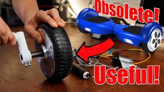
- I found a discarded hoverboard, so I removed the wheel motors and am trying to get these to spin from scratch. This video is a circuit to test the operation of the hall effect sensors. This is my first ever CZcams upload, I plan to do many more as I go. All comments and criticism welcome. My uploads will never contain any fancy graphics, long repetitive intros, or music of any sort, and will eliminate as much of the boring stuff as possible (if I have to solder 30 pins, I will not make the viewer watch me do each one)
- Věda a technologie


Nice video. I’m taking one apart too and was wondering about where the hall sensors were and how they work. Keep posting.
Thanks for your first video, I'm in the exact same seat! I have a hoverboard that I need to fix or re-purpouse so looking forward to learn from your vids
In this case, I was not trying to fix the hoverboard, in fact, I bought a perfectly working hoverboard and tore it apart so I could experiment with the motors.
keeo on charging bro
you ever finish this? im curious what your completed DIY controller looked like
No I haven't finished, but have since learned much more about this subject. From what others are saying (Gerald Morin, etc.) about these motors, what comes out of the controller is not amperage or voltage, so to speak, but a signal. I have since concluded that what's going on in the microcontroller to produce/control this signal is thus far outside of our understanding. So the next time I try to run one of these motors, I will build an analog controller like I do with my other home made motors, the attempt at using the mosfets and the microcontroller were virtually complete failures, could only jiggle the motor a bit, not even worth posting the videos of the project.
i think the lights should also light at the same time with te left two look at this vid at 03:30 czcams.com/video/tD5EO96BHFs/video.html
Interesting video, just watched it, thanks for posting
"These aren't motors" Stop trying to sound smarter than you are.
Nobody here is trying to 'act smart', but in order to try to understand what drives these motors, we need to not confuse them with the old and completely different style of 'electric motor'. These 'motors' are run by resonance, or a signal, so to speak. The electric motors of old gobble up tons of current when loads are placed on them, whereas these drum style variations do not, because these are not driven by amperage, and as of now, nobody has been able to explain just how this signal that drives these motors is produced and controlled. Perhaps you in all your wisdom could explain it to us? We would appreciate it
You want me to go into detail what a 3 phase motor is? Plenty of videos about those.
And before you ask. Notice the multiples of 3 for coil count.
@@Marc_Wolfe I understand they have 3 sets of coils, or 3 phase, I've studied the output from these motors on the oscilloscope, knowing they are 3 phase motors doe not explain how the signal for running them is created or controlled, as this is done within the microcontroller itself, which might as well be on Mars because we can't go inside the microcontroller and see what's happening. Same goes for our power lines, coming out of the pole transformer is the household electricity we understand, but what goes into the transformer is something else altogether
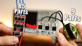
On the hoverboard I took apart, the microcontroller outputs the same 3 phase logic, then that went to a multi-mosfet package that prevents short circuits (making sure high is disconnected before driving output low, etc). 6 wires right? What goes into most pole transformers just higher voltage.
Thanks for your first video. Nice and simple. I was wondering if I could Double up hall sensors (2-4 wheels with one speed motor) well you answered my question inadvertently. I’m your first subscriber and look forward to many more. Thanks
Correction to the video, the 3 outputs from the sensors are yellow, blue, and green. Red is the power supply, and black is the ground
The hall sensor dont have a index?
The hall sensor PCB (3 sensors) all share the same ground and hot, and each sensor has its own output (5 wires total for the PCB)
Hey john great video i was wondering do i need the hall sensor what is it broke in my motor?