DIY Active Differential Probe for your oscilloscope | Do-it-yourself electronics

Vložit
- čas přidán 13. 02. 2023
- An active #differential #probe designed for the measurement and visualization of waveforms of mains voltage (or at mains' voltage level) on a common #oscilloscope without running the risk of frying the scope, the probe, or worst yourself!
In a previous video (here: • Easy DIY passive #prob... ) I've showcased a passive probe, unlike that one this active probe uses only one input channel of the oscilloscope.
The probe run on a 9V battery that lasts about 20 hours (based on Duracell's data sheet calculated for the current drawn by the circuit.)
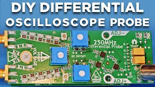
It features an input impedance greater than 4MΩ, an output impedance of ~50Ω and an attenuation ratio of x200 (200:1). The theoretical maximum input voltage is 800Vp (given by the voltage limit of the resistors used in the attenuator). This allows to take measurements not only on common 230/240Vrms but even at 380/400Vrms (used in Europe), including phase-to-phase on a three phases system.
BEWARE that if you try to make this project yourself you'll do it under your own sole responsibility, I'll take no liabilities! Keep in mind that the circuit's performance and limits heavily depends by the components used and how the circuit has been made. I mounted two of the four resistors of the attenuator on the PCB and has been covered with an insulating resin that is NOT visible in the pictures.
The probe is built around an LM4562 in IA configuration, and a resistive attenuator. Tests confirmed that there is no need for capacitive compensation since the input capacitance is remarkably low (less than 2pF) and the frequency range of interest is about mains frequency (50/60Hz) and its harmonics, so rarely there is the need to read frequencies above 20Khz.
I hadn't the possibility to test the probe for its actual bandwidth, though.
For the sake of simplicity I used common 1% resistors (with 20ppm/C) rated 250V. The "high" voltage must be well separated by the low voltage part. The key point of this probe is the link to ground, or PE (Protective Earth) that provides its safety. It works on both TT and TN systems. The PE is also carried by the oscilloscope, but the provision of a separate connection for grounding (the green banana socket) is important in the case of fault of the cable, the use of a battery powered oscilloscope and the case when the plug is disconnected from the scope.
This probe MUST NOT be used where the line is not protected by a GFCI, RCD or RCCB.
Full series of #Electronics: • Hands on electronics - Věda a technologie


I had to take down the initial version of this video because it was defective, lacking a piece, so I had to re-encode it completely. Sorry for the inconvenience.
Many thanks to those who informed me about the issue.
A hand drawn PCB. It`s been a long time, and that drew some memories. Thank you.
Also, this was a good reminder that you can still build something quickly and with components out of the jar.
Exactly you got the point. 💙 Thanks for commenting and greetings from the Alps.
Nicely done! Thank you.
Great material, thank you so much!!
Thank you for sharing all these information with us
Thank you for a great video and the fascinating development of the circuit. Subscribed.
Very nice, congrats!
Grato!!!
Precisely what I was looking for .
Wow nice! I knew the sleeve of LM4562's I've had for years would come in handy one day! In all seriousness, I've been needing a differential probe for a while now but never wanted to shell out the tons of money for one. It's just one of those things I need but, not that often. I'm gonna give this a shot. Thanks!
Let me know how it went.
Greetings from the Alps.
Thanks for bringing attention to LM4562. I like it, I'm going to order some :)
Excellent!
Great Work !!!
Thanks
@@AccidentalScience Professional !!!
Nice job.
Thanks!
bravissimo!
Pausing to comment on a couple of things:
quad opamps give you 4 of them per package. There are useful things you can do with one more opamp.
Two 9V batteries can also be used so you have +/-9V to work with.
A trimmer resistor can be used to make up for the fact that your resistors are only 1% unless you have a big budget.
To trim the resistors you apply the same signal to both inputs and trim for no output.
Thanks for commenting. Cheap trimmers can be a source of problem as they vary with temperature much more than regular resistors. Good trimmers are immune but they are way more expensive than 0.1% resistors. So I preferred to select pairs among a bunch of 1% resistors. I don't remember if I mentioned it in the video, sometimes I take for granted things...
Cheers.
Really glad I stumbled across your channel. And hope to see you get a lot more followers and attention in the future.
Regarding this build... The weak link is definitely the Duracell battery. I've lost thousands of dollars of test equipment and other associated tooling to Duracell batteries. Some of my favorite portable lab equipment over the years. LCR meters, pricey multimeters, handheld Scopes.... And all kinds of other random things.
Technically all alkalines are risky....But Duracell is the worst for some reason. Which is a real shame because they used to be the best for a very long time.
Now i will only use the Energizer ultimate lithiums... They're not rechargeable and they are more expensive but I've never had one leak. And they seem to last three to five times longer than your standard Duracell alkaline.
Luckily most portable test equipment these days is being built with internal rechargeable lithium cells. Most of which are standard 18650s that can be swapped if they ever wear out. But they're still a surprising amount of medium to high-end equipment that doesn't have its own internal rechargeable battery. For some crazy reason 🤷♂️🤦♂️
I really enjoy the videos and look forward to more content from you in the future!
Thank you. Lithium batteries are expensive at the point they may shift the cost of the whole equipment.
Nicely done, good job. Would you provide a "final"schematic to this ? Would be interesting to do some tests with.
Best regards
Thank you. Yes I will ...one day my website will be ready ...hopefully! And there I'll put a lot of material, including this schematic.
Cheers.
Someone stealing electricity the sneaky way “wave clipping”.
Hi, nice video,
what sort of pen/marker did you use to mask the PCB before etching?
It's "Dura ink 5", it's similar to paint pens used to mark on metal but with a finer tip (about 1mm). Alternatively I use a quill pen with ink for metals, which gives better results, in particular ink resistance against the acid and water, but it's harder to master.
@@AccidentalScience Thank you :)
Where do you get the resist pen I've tryed some with no good results ?
I use a paint marker pen, with oil-based ink. A few are available with a reasonable fine tip (about 0.8mm), specifically what I use as resist pen is a "dura-ink" long thin point made by Markal. It is labelled as corrosive but it is not that corrosive on copper. Best results are achieved using an ink for metal stampers and a fountain pen, though it is a tad more cumbersome to use. Also try to give a look at this: accidentalscience.com/12/Printed%20circuit%20board%20techniques.html
thanks i found some and will give it a try
what is the max frequency can be read by this probe?
@@endremurti as you can read from the related article on my website I haven't done a proper bandwidth test but using a known frequency and amplitude of 1 meg I've been able to see no attenuation.
@@AccidentalScience oke 1mhz is more than enough, i need some of such device to develop my smps
@@endremurti actually is not that much if you plan to use it on an SMPS. You'd be better off adding the capacitive compensation provided you purchase the right capacitors (you need almost 1000v to be safe) made in EU or in US.
@@AccidentalScienceok ,you mean like atc capacitor for high power rf?
By the way thanks for share this project ⚡️
The compensation capacitors should go across all 4 input resistors, not just one of them as you have it, IMHO. It has almost no effect when you put it across just one resistor. It should be safety cap.
I'm on a mobile so forgive the short answer. Under frequency domain capacitors can be seen as resistors (1/(2πfC)). In probes the series capacitor (parallel to the series resistor) works to form a reactive divider with the parasitic parallel capacitor (the one that is in parallel to the input). Ultimately it doesn't matter where the series cap is placed as long as it adds up as "frequency depending resistor".
Thanks for commenting.
@@AccidentalScience Well, it's not the same if you place that compensation cap across 1 resistor, or you place this cap across that whole array of resistors.
I was out of my studio and was hard to give a good reply with the mobile phone. And your comment deserves a deeper reply because it gives the opportunity to clarify a doubt that others may have as well.
Yes, of course it is not the same of having the cap across 1 resistor and with another resistor in series. Typically probes have a capacitor that bypasses entirely the input resistor, to form a capacitor divider with the parasitic capacitance of the input port. Adjusting for the right capacitance it can provide almost a flat response.
Here however I did not want to have a capacitor that bypasses the whole input resistors. That was because I'm worried that someone may copy the project and put a cap rated for not enough voltage!
The device is anyway limited in frequency because of the OPAMP and the use of cord probes, and I expected it to be below 500KHz, which is more than enough to measure mains voltage. Under these constrains having a compensation capacitor on just the last resistor does not change much the final result, because in any case you have a roll-off frequency.
Using SPICE I've seen that a capacitor of .05pF in parallel with the entire series of resistors (2.15M) should be enough. That's likely the parasitic cap across the very same resistors. Also, I've seen that with a cap of .5pF / 1pF across the last resistor (470K) gives a nice roll-off at 1.6MHz.
Indeed I had the chance of testing the probe for the actual bandwidth, without compensation capacitor it is about 300KHz, with 1pF cap (parallel to the 470K) it reaches 1MHz before rolling off, with a slight overshoot centered at approx. 400KHz. The same 1pF cap in parallel to the whole series caused an unacceptable increase of the response above 100KHz.
So as a final consideration I'd say that it doesn't worth to have a compensation capacitance given the intended application.
Cheers.
I built this probe, but I see the same "clipping" (but it is no clipping,just a deformed sinus), I added a small capacitor over the inputs of the opamp, so form pin 3 to 5 , then the sinus is must better, (still not prefect., but of course this will change the gain factor , so to compensate this I change the resistor 10K from pin 7 to 6 , to a restistor of 6k8 +10k potentiometer , now i have a variable gain, and a acceptable sinus
but i don't have enough knowledge of elektronics, why this "clipping" behaviour exsist?
You must have made some mistake somewhere. The capacitor between the non-inverting inputs of the two opamps doesn't make sense. I'm on my mobile and I can't give a complete reply now. Clipping may happen because the output exceeds the supply voltage (less the voltage drop of the internal output drivers). This can be caused by a wrong input attenuator, wrong feedback resistors. First check if the input attenuator is correct by measuring with an ohmmeter: each branch, branch toward gnd and end to end. Also test the instrument with a low voltage source before attempting to read the mains voltage! You *must* be sure the attenuator works properly! This is very important.
Thanks for fast reply, I have measured the attenuator well, resistance, but also applied a voltage, and at the end the rest voltage, this was correct, as soon as I have time I will take a picture with and without a capacitor, also a picture of the sine measured with a transformer 230 to 12 V ac, the voltage certainly does not clip, power supply is + and - 12 Volt, the peak peak does not exceed 3.5 Volt
So you connected a 12V dual power supply, with + to +B, - to -B, and GND to GND? So skipping the battery and the OP07 (or LM741) altogether? Also, the input probe + (the one that goes to pin 5) and input probe - are hooked to a 12VAC source, and you get 3.5Vpp in output (pin 7) ?
If so, something doesn't add up. With 12VAC rms (16.9Vp) at the probe inputs, the output at pin 7 should be 0.17Vpp (or 0.085Vp).
As said the clipping can be caused only because the voltage swing of the OPAMP's output exceed the available voltage, that is given by the power supply voltage minus the internal output drivers' voltage drop. For the LM4562 the voltage drop is ~+/-3V with +/-15V supply, so with a +/-12V supply the max swing would be +/-9V, in reality it is a bit less and should be around +/-8V. You have plenty of voltage and you should not have any clipping. Check the actual voltage at the pin 4 and 8. Be sure to check both in respect to GND, *and* between them. Check the voltage is clean and stable.
Also the attenuation ratio/gain ratio doesn't seems to add up properly, as mentioned above.
First, connect probe - to one pole of the 12VAC source, and GND to the other pole. Then check at pin 3 the voltage and compare it with the voltage between GND and the probe - . You should have 0.043Vp at pin 3 with 16.9Vp at the probe.
Do the same with the probe +, checking the pin 5: you must have the same values as for probe - .
I will not able to reply for the days to come, so if you reply something here I will not see it before next week.
AFAIK it is not possible to upload pictures here, so I'd suggesto to comment in the related topic at my facebook page where it should be possible to upload pictures.
@@AccidentalScience yes i complety removed the op07 cirquit and replace by a double supply -12 and + 12 Volt (measured -11,95 and +12,02 V).
I also measured the resistance of the attenuator
again I have done a lot of measurements, and find out that my incoming mains have not a nice sinus, but some topping (looks like clipping), I put your design on the scope with a signal generator Sinus, then the sinus is perfect. measured with 2 scopes, no difference, and measure with a transformer 230/12 V, also there the sinus have some topping.
I also removed the small capacitor form pin 3 to 5 , and checked the signal, without I see the "real" mains with some cilpping/ topping, with the capacitor is see a sinus, so the capacitor is changing the real signal!
Conclusion: the design of the probe works perfect, only the mains is not so nice..... (searching on internet, I see a lot of people have the deformed sinus at home). the "variable gain 6,8K+10 K, (instead the 10k resistor), is nice. Best regards Wim
@@wimlemson6498 fine, I'm glad you found the problem. A variable gain is not a good thing because it reduces the accuracy of the instrument. Greetings.
Why not use higher bandwidth differential amplifiers? Instrumentation amplifiers have unnecessarily high input impedance and low bandwidth.
Higher bandwidth, such as? May you suggest something?
@@AccidentalScience 2 x THS4631 for the input buffers, and a THS3491 as the differential amplifier. Your "design" has very low bandwidth and terrible slew rate for a general purpose differential probe.
Dear, my probe is not for "general purpose", it is meant to measure AC mains! Look at the probe cables, do you really think those cables would fit a measurement in the range of megahertz? Anyway, thanks for the indication of the THS4631, it is relatively more expensive compared to the LM4562, and has worse THD while featuring ~4 times larger bandwith product. So it is an interesting component, and indeed I made an attempt to purchase some pieces a year ago but I gave up as they were constantly out of stock at the time.
Back to the probe. My probe, which indeed uses a very classic configuration so my "design" is very limited here, uses just a single OPAMP. It doesn't even feature a proper compensation because it would require capacitors with certain specifications about the ability to withstand almost 1500V with no leakage. I fear people may try to replicate the project and purchase those assorted bags from Chinese sellers on Amazon, components that I wouldn't trust even at 100V.
So I preferred to be conservative and keep a moderate compensation. This provide a probe that has a bandwith (-3dB) of about 1.8 MHz and 10MHz at +/-6dB, which I dare to say should be more than enough for a probe meant to measure AC mains waveforms, including high order harmonics and spikes. And it is dirty cheap with easy to get components.
Cheers.
@@AccidentalScience ... The THS4631 is a FET input opamp with 1000V/µs slew rate. The LM4562 has like 20V/µs slew rate. It's a whole different class of amplifier. If all you want to do is look at your 60Hz mains, anything will work, but it's pretty useless.
No work? You deleted schematic you blog?
I'm migrating from an old blog, that's why you can't find all the articles. Subscribe the newsletter to get notice when the site is up to date.
Hi, awesome video. New to the channel too. You would know if this design is suitable for probing on SMPS? As far as I could tell the SMPS I am messing around with has a fOsc of around 100kHz can't say that's what the MosFETs are being switched at but I'd say that's around the frequency that would be used. I might make the Altium design too. It's on czcams.com/video/zQDLY-ot4eo/video.html. Possibly over specfor what I would use it for but I think it will make a for a fun project to do for myself. I am asking since If this design is adequate as well, I'll totally take on it and maybe make it in KiCAD too. Wishing myself luck too. and Happy holidays!!
Sorry for the late reply: your comment was been held by YT because of the included link and I had to approve it manually.
The probe designed by @Altium Academy similar to mine in its essence: a couple of attenuators that refer to ground, and an instrumentation amplifier that picks up the signal difference, buffer it and amplify. Mine is way simpler than the one made by Altium. My probe's goal is to measure low frequency (from memory bandwidth should be around 10 MHz), while Altium's design goal is 250MHz. A whole different beast. He uses ADA4817 that have a whopping 1050MHz Vs. LM4562's 55MHz, which is a more common chip used in audio applications that one likely have on his shelf.
So to answer your question, while my probe would take the voltage you find in a SMPS it is not the best fit for the frequency you have, and I suggest to go for the Altium's design for that purpose.
Happy new year.
@@AccidentalScience Your design will be good enough for most switching mode power supply trouble shooting. Debugging a switcher involves some amount of looking at the waveform and then working out what the waveform really looks like and then deciding if it is correct. I you look at the points with the small swings on them, you have to remember that right near your probe is a huge swing happening just about in step with what you are measuring. The voltages on the windings always have some ringing on them so they look ugly.
@@kensmith5694 I totally agree. It is more than enough to check if there is a proper switching signal to the mosfets/transistors. It usually never goes above 200kHz. Mostly a lot less than that. Maybe around 50kHz. So this probe would be absolutely fine for repairing SMPS.
Circuit is pronounced sir-kit, not sir-ku-it.