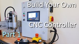
Build Your Own CNC Controller, Part 2 | DDCS V3.1 | 6040 Router

Vložit
- čas přidán 27. 07. 2024
- Build instructions for an offline CNC controller based on the 4 axis DDCS V3.1 controller, part 2. Wiring diagrams and parameter settings for the controller and VFD can be found on my website, as well as the bill of material:
uptimefab.com/2021/01/11/buil...
Note: the Noctua fan is only available in 12V, not in 24V, so a step down converter or separate 12V supply is needed. See video part3 for updates to the controller and check the pinned comment on that video for best practices.
0:00 Intro
0:20 Mains disconnect switch and air inlets
01:38 Noctua case fan
04:03 Mains Voltage Circuit
05:11 Wiring Stepper drivers
08:24 USB plug
09:14 MPG wiring
11:39 VFD Wiring
13:57 Terminal blocks
16:03 Tool Probe
17:34 Wiring the 4th axis
20:22 Spindle RPM measurements
20:48 External E-stop wiring and test
22:58 Dry run of the controller
Link for cable clip: grabcad.com/library/flat-cabl...
If you have any comments or questions please let me know.
Robin - Věda a technologie


This was just a piece of marvel. I'm just figuring out how should I wire all of my stuff to the BIG cnc-router I'm currently building. This gave me many ideas to make it better. Thanks!
Excellent video, very tidy build, I have just bought the DDCS V3.1 so this is very welcome information, thank you for taking the time.
This is possibly the best video I've seen on YT. Clearly explained and not a word was waisted. Thanks do much for taking the time to inspires us!
Thanks to you for taking the time to write such a nice comment!
brilliant build, you can get din rail mounted thermostat fan controllers so you could even only have fan come on at 30 degrees instead of constantly running.
Man I subscribed just based on how clean my guys wires are. This is how it should be done. Looks fantastic. Great work man.
Nice level of OCD in your wiring and attention to detail as an Elec Eng I approve :)
I like the build, doing something similar, but was unsure on my enclosure, until I saw yours. Oh the crimper needed is called a "B" crimper and there's a few different sizes that I use.
You engineerd this past my competence level.
Great video.
Very good build and explanations in the video - I had been wondering about the DDCS V3.1 but ended up going with the Duet 2, which is still more suited for 3D printing. You've give me some ideas so thanks again for sharing.
Thanks, much appreciated. I remember actually having seen some of your videos as well, good stuff!
Great build! Very orgininized and nicely presented! Nice job!
Rocking the background music as I watch your build
Excellent work, I'll be revisiting this series while I'm putting together my own electronics case
Thank you! Glad to have been of help.
very nice, the only thing i would have said has already been addressed and that is the grounding on shield cables
Again Thank You for the GREAT VIDEO...
Other then not grounding the shields of the cables for a drain and not seeing if you ran grounding wires to all the metal components in the case this was a great mini series. I feel as if you missed a possibility by putting the DDS in its own smaller remote box and running a cable to the bigger case. This would allow you more freedom as to where you can mount the DDS as it would be smaller. GREAT JOB!!
Thanks, very useful feedback. Indeed having the DDCS in a separate smaller enclosure would be a significant improvement in the ergonomics department. I now have the cabinet below the table that the router sits on. Going though the menus while sitting on your knees is not ideal. If the case is wall mounted at eye level it would already be an improvement.
Outstanding videos ! Perfectly done.
Excellent video, thanks for sharing this.
Nice built, that meanwell brand is very good fot price, i have used it.
Ground your spindle (to the controller ground) and you wont (shouldn't) need to clamp the tool when using the probe. Very well done, thanks for posting.
Never mind, I see you did that in part 3!
Thanks anyway for the tip!
Excellent.Thank you for this video ❤️
Note: For proper shielding of the stepper cables, the shield should be connected to ground on one end inside the cabinet. Connect all ground wires to a single point / terminal. See video part3 for updates to the controller and check the pinned comment on that video for best practices.
And a run ground from machine frame to controller. The metal plate in the e-box is used as ground plane shielding all the electronics. Adding ground cable to every switching p.supply with metal frame touching the plate is the wrong way because creates a ground loop . You can use s/stp s/ftp cable as signal cables and connect the shielding to groundplane as start point of the ground trees.
About 4th Axis in Fusion360:
A rotary/rotational axis may have been added to a three axis machine. Most of the post processors available in the HSM post processor library are set up for 5 axis code. The 4th and 5th axis are disabled by default.
Great stuff as always. I wish I was as tidy with wiring... Just burned the lathe control board because I was testing & moving parts when the lathe was on 😭
Ouch, that sounds costly. I have also fried stuff before. Oh well... failing is a good way to learn, or at least to find out how not to do something. Thanks for the comment, stay safe! :)
Awesome work man , one of the besta O have seen about cnc , I hope to see more videos related to cnc, best wishes !!!
Thanks for your compliments! Nice to see the videos were useful. I have been a bit occupied with other things lately, but hope to release some more CNC related stuff in the (near) future. Cheers, Robin
Nice cable management. I would suggest a metal plate for the connectors to common too (inside the case is fine). Connect the wire shields to the connector housing (which you seemed to have ignored) which will then connect to the metal plate. Earth ground the metal plate at one point. The whole idea of the shielding is to provide a faraday cage for the inner wires. Only earth at one end in this case. If you have noise issues, a cheap fix is aluminium foil with kapton tape over it and stuck on the inside of the case (Earth at one point too). Copper tape is better but very expensive. If you can get steel or tin foil instead of aluminium, even better. Steel being best.
Hi, thanks for the very practical and useful tips on grounding. Others have commented on this as well and rightfully so. I have not had issues without proper grounding on this new controller, but it is better to follow good practice to prevent having to troubleshoot weird issues. I have just wired the first cable shield to ground. Many more to go. I will probably do this at some point in the near future.
Nice job sir. Wiring is ultra smooth
Thanks!
Suscrito.
Cordial saludo desde Colombia.
Uno de los mejores tutoriales educativos e informativos para montajes de control CNC
Ordenado, limpio y muy explicativo.
Muchas gracias por compartir y por tu valioso tiempo dedicado a ello.
Bendiciones de salud.
I had to google translate your comment, muchas gracias for the nice feedback!
Good work. another suggestion. Ideally you want the airflow to move across the heat sinks of the drivers.. right now your drivers are essentially blocking the flow of air. maybe install another set of fans up top...
Thanks, indeed the air flow path is not ideal due to the layout in combination with the size of the cabinet. I did not want a fan on top exposed with possible debris or chips falling into the cabinet, so that is why it is on the side, but I fully agree the air flow path is not optimal. For a next project it might be better to have a larger cabinet. Makes wiring easier as well. I have measured temperature on the drivers after being on for a while and they seem to stay within normal temperature range. Will update if there are any issues later.
With a bit of solderin iron you can get the wires firmly tight to the connectors, otherwise they can slip.
Good catch, one of the wires came loose, probably due to me not properly heating the wire and connector when soldering. So far the rest are still ok. Keeping my fingers crossed
Cool info, thanks :)
Awesome. Thank you.
Outstanding video
First off, nice build.
To your connector problem, wrong pliers used, went through the same problem you had, correct pliers fixed the issue.
For your PTFIX blocks and terminal blocks, by the looks the ones you have are the PT 2,5 if i am correct, try the pt 1,5 ones, way smaler. And you do not need any feruls on the wire for these, fine strandet is fine without any termination, just push the release in with a screw driver, insert wire, done.
Hi, thanks for the useful tips! It makes perfect sense indeed that not all type of connectors can be crimped with the same cheap pliers.
I just looked at the different ptfix options again and indeed the 1.5 version is significantly smaller and 1.5mm squared is enough for this application. I already thought the ones I had were small!
Excellent, well done
Thanks!
Australian electrical standards mandates that brown is used for mains power active, Blue for neutral and green/yellow for earth. :)
First off I want to say thank you for putting together these terrific videos and the detailed write ups on your website! It has been extremely helpful for my CNC project! One thing I’m confused about is why you have a dedicated power supply for the safety circuit? Couldn’t you use the other 24V power supply to also power the contactor?
Hi Tim, thanks! Please see the discussion on this topic below video part1. In summary it is because I want to prevent damage to the DDCS due to the voltage spike when the contactor is disengaged. Not sure if this is needed, but I do this just to be safe. Meanwhile I have also bought a surge protector (siemens 3RT2916‑1DG00) which can be plugged into the contactor to reduce the spikes. With that solution it might be safe to also connect other electronics to the same power supply. This is at your own risk though. I do not have a scope to test this but according to the Siemens manual it should reduce spikes down to less than 1V. Cheers, Robin
@@uptimefab7412 Ah, I missed the comment from the previous video! That makes complete sense though. Definitely would be better off spending $15 on another power supply then risking burning out the controller! Thanks for the info!
Top effort and thanks for going to so much effort with the video. Five things I would have done differently
1/ Nutserts
2/ 240v control for contactor
3/ over strip your your cables for your connectors and tin them from the top. Then trim to size and then insert right up into the connector and solder lastly.
4/ Keep all heartstrings as short as possible for flexibility.
5/ probably the most important, use cable duct for running cables strategically placed for connectors.
Top effort tho.
Cheers
Thank you for the tips! These should indeed lead to a cleaner build. A note on the contractor: 230VAC (or 240) works great and had advantages such as availability and cost as there is no need for a DC power supply. The main reason I went for a DC contactor is that I have both a panel switch and an external E-stop on a long wire in series with the contactor. These could be 230V but I feel more comfortable with a low voltage wire running to the Estop. As mentioned one can also connect the Estop to the dedicated port on the controller, so in that case only the 230V pushbutton remains and you end up with mostly advantages for the AC setup. Having said this, I am happy for now with the DC contactor. Also used that in my later lathe retrofit since there was also a long cable to the contactor, which I prefer to have low voltage.
@@uptimefab7412 I've never used the set square like you did. Instead I painstakingly measure off everything. That makes life so much easier the way you did it. 🍻
Really liked your video. Bought a chinese 6040 and could never get it to work properly. Specially the limit switches / Probe. I have decided to change the controller and the stepper drivers. Your video gives me hope. My problem is that the board that I got has the "controlling" part and the drivers all in the same board.
Thanks! Good luck with the conversion!
Thank you
Great work. I am working on a very similar build for a customer. The cable management is top notch! Love that cabinet. What's the brand?
Thanks for your comment, much appreciated. The cabinet is the Famatel 39145. If you need info to other parts they should all be listed in my website article linked in the description. Somewhere in the Middle of the article. Best, Robin
BTW if you ground your spindle with the 4th pin you won't need to use the clip on your probe
Very nice!!
Does the DDCS controller allow you to slave the A axis for a Dual Y Setup?
Thanks For the Detailed video and What A control Box! Great Job!
Unfortunately a dual y axis is not supported directly by the controller. You could wire 2 stepper drivers into the y axis port but of course you would not have the ability to work with a separate home switch for each motor to align the axis. I read somewhere that it might come in a firmware update for the expert model, not sure if or when this would happen and if they will also do this for the V3.1. Thanks for you feedback, much appreciated!
Beautiful work and a great video. Incidently, your mains wiring colours are exactly right for the UK (and so presumably for the Eurozone too) ie Brown for live, Blue for Neutral and Yellow/Green for earth. These colours replaced Red, Black and Green/Yellow here many years ago. I'm not sure of the logic, but Red clearly signified 'Dangerous' and I suspect it was decided that Brown was closest to this for the new colours as Red and Blue are traditionally seen as opposites. Personally, I think Blue for ' Electricity', Black or Grey for Neutral and Brown for Earth would have been more logical (though clearly it would not be wise to wire any equipment in accordance with this 'logic'!)
Thanks for your insights! Makes sense indeed to stick to the standard colors for mains to avoid confusion.
I am in the process building a cnc and enclosure your video were very helpful. It would be helpful to see links to items used in the videos (tools, materials, screen and enclosure) thank you.
Hi, thanks for the tip. I hope you did find the bom list in the article linked in the description, but this would I deed be easier, so you would have a starting point to search for a supplier.
----- EDIT: I have just updated the bill of materials with hyperlinks to where I bought the items. Some stores may not deliver to your country, but at least you have a starting point and in many cases there is also a datasheet on the linked store.
Hope this helps,
Robin
Love it 👍
I'm gonna buy me this controller and upgrade my plasma.
I'm interested in the 4th rotary axis too. Do you have a video explaining the 4th axis setup and configuration please?
Thank you! The settings for the 4th axis in terms of steps per revolution are in the PDF of in the website article. I don't have a well documented procedure for setup as I don't use the 4th axis. Bought it with many projects mind but keep delaying in favour of other projects. There is a great video by Charlie Sarsfield that I would recommend: czcams.com/video/nYm2pVXMVSc/video.htmlsi=o9yHEwzHt17nedLq
great !
Hi, thanks for the video, very informative, we also purchased the same device to control our CNC however we have a problem with the limit switches we have the PSN30-15DP and its not detecting or turning on the switches we went according to the wiring diagram, I would appreciate and help in this regard, thanks Ashley
Hi, I have just installed mechanical homing switches (similar connection as limit switches) and they work fine. Connection is different though for inductive sensors, however parameters should be the same. Have you checked if parameters #52 up to #55 are set to 1? #400 up to #407 should be 1 as well. Check #408 up to #415 if the electric level matches your connections ( normally open or normally closed). Are they connected per section 2.6.2 of the manual? Have you checked if the switch works in the IO screen on the DDCS controller? That is all I can think of at the moment. Let me know if you had any luck with this.
Robin
Thanks!
It's a pity Autodesk is slowly removing more and more features from the Free Licence. I think I'm gonna stop using it altogether and learn AutoCAD
Спасибо!
Great work , how much cost all equipment cnc controller
Muchas gracias por tu generosidad, excelente trabajo, felicitaciones, por favor me podrias decir el diametro de los cables que usaste para las conexiones de las señales de paso de los drivers que se conectan a la controladora ddcs v3.1, por lo que veo son cables delgados, muy agradecido, exitos, saludos
Hi, if I understand correctly after google-translate, you are wondering what diameter wire I used for the signal wires from the DDCS to the stepper drivers. These can be very small, I used 0.14mm^2. However, this is not advisable, since even with the smallest ferrule it is difficult to get them securely tightened, so the ferrule stays in place. For a later build (my lathe) I used the larger 0.34mm^2 wire for signal wires. Much easier to work with and ferrules are more securely tightened. Note that I do not know what the industry standard is, this is just what I use. Also i would like to note that for the wires going to the stepper motors I am using much thicker wire (0.75mm^2) since they carry high current.
@@uptimefab7412 very grateful, thank you very much for sharing your knowledge, my best regards to you to carry out your projects and continue helping with your knowledge, please, if it is not too much to ask, can I bother you?
in the future to complete my project, I also want you to know that I am copying your project, I hope you are not offended, I am very new to this, I do it to learn in my free time, your project is an example for many people who want to learn , I am from Argentina, here it is very difficult for me to get the materials you used, but I am getting it little by little, when I have it finished I will show it to you and share it with you, I hope it turns out well, congratulations and thank you very much again, for everything, sorry If something was translated wrong, I'm using the translator, good luck
6 sensors are required for (X Y Z)
And 3 extra sensors for Home (X Y Z)?
Or the Limits can be set as Home?
Are the Home required?
Great video, great explanation.
Both are possible. You can combine limit switches with homes switches. In that case you need to set a parameter to automatically disable the limit switch function during the homing cycle. After homing it will act again as a limit switch. I have also placed home switches in the meantime. When using soft limit function in the control, no switches on the other side of each axis would be needed. Still have to test if this works well enough. Switches on both ends is probably the safest solution.
@@uptimefab7412 Last night googling, I found the official forum (eureka)
And they talk about Limits and HOME
bbs.ddcnc.com/forum.php?mod=viewthread&tid=82
Now the problem is adjusting those settings ...
Thanks for your video.
Your ensemble was perfect.
Great video , just have one question regarding the wiring of my spindle as I have a 'bitsensor' board that I am replacing with the DDC3.1 ( 6040 cnc unit) . I have a wire coming from a location called AVI, what and how is this wired in relation to the same break out port you use. I have this also, I see the VSO and M03, and Gnd, is this all thats needed? I seem to have a forth wire...for AVI...Its labelled AVI-10V-Com-FWD-.
.Thanks again, Rich
Hi, this could be an Analog Voltage Input and I assume this is coming from an output terminal on your current controller used to control the spindle speed. In my situation with the nowforever VFD I am using am output from de SZGH controller to connect to the analog input "Ain1" on the VFD. The SZGH outputs between 0 and 10 volts for min and maximum RPM respectively, based on the RPM you select. See wiring diagram PDF in my website article. So you would need to look for the analog 0-10V input port on your VFD. It may not be called Ain1, but might be some other name. Most VFDs have this input port. Long answer, I hope this answers your question :)
I am from GREECE
You do a lot of work and thank you for your work,
We who do not know also learn.
I'm new to DDCS4 V3.1 and do not know how to create a file with the code that works, maybe you can help me send me an etymology file so I can figure out how? Can I send you a plan to show you how to become one?
Thank you very much
Fotini.
Hi, the manual has a comprehensive list of M and G-codes with explanations and it even includes examples. I think this is the best place to start.
good video, how is the performance compared to Mach3 ?
Hi, I have only tried a couple of test programs so far, they seem to run fine. Have not experienced any issues or lost steps, which was one of the main reasons for this, so far so good.
good job! where did you connect the cable shield?
Hi, I connected the cable shield to one of the unused pins and routed that wire to the grounding bar. This is a single point where all found wires are connected. Note that it would be better to place the connector in a metal plate. That way you can just fold over the cable shield, which connects it to the outside of the metal connector. This in turn is fitted in the metal plate. You can then run a single wire from the metal plate to the ground bar to ground all connectors.
Looks great, but why didn't you add a 4th wire to the spindle cable to ground the spindle motor ?
Thanks, I am not sure how to connect ground to the spindle yet. There is a 4 wire cable running to the spindle, but the 4th pin is not connected to anything at the spindle end. I would have to remove the top of the spindle to actually connect it to something inside. I am not sure if the coolant lines are opened when I take off the lid so I am hesitant to do this. Maybe a general ground point to the spindle or other part of the frame is an option and run that to the central ground inside the controller cabinet. Please let me know if you have any tips on good practices for grounding the spindle.
@@uptimefab7412 on my aircooled spindel I was able to take off the motor top cap easily and find a good ground point. In your case maybe break out the ground wire just before the plug entering the motor and simply crimp on a round lug which goes to one of the motor clamp bolts then ? Or just run a fully separate wire to somewhere directly in contact with the motor at least. It's not double isolated so the ground is your only safety.
Note that the old black box too lacked a proper ground for the metal case itself...
Thanks again, I will have a look at what is the most practical solution in my case. The machine as I got it from the supplier was probably not the best example of a properly grounded machine. I have learned a lot during this project on grounding (and still have a lot to learn). It will probably not be perfect but hopefully safe to work with.
Great video, nice work. Which postprocessor i have to use in Fusion360?
Thanks! The standard mach3 post that comes with fusion works fine for me. Check the comments under the website article linked in the description for a modification to this post to add a delay for spindle ramp up, but you can also use it as is.
Just a thought but shouldn't the spindle use a different type of connector if the control box is powered on but the spindle is disconnected, youll have exposed live through the pins on the outside of the box. I think you should be using a ws series connector instead? (It has a socket on the through panel bit and pins on the cable bit) Also isn't a 1500w spindle too high current for the 5a rated gx16?
Excellent point. It would indeed be a good idea to get a connector with higher amp rating for this. Also, I don't like that it is now possible to plug your stepper cable into the spindle connector. Not exactly poka yoke. I just copied the way it was wired in the old controller to keep it simple, but there are better ways of doing this. This means controllers are actually sold wired like this. I will try to get a different style (female) connector with higher amp rating. Thanks for the feedback!
@@uptimefab7412 I would recommend something like a ws20 connector. Works the same way but is the other way around (socket on the through panel, pins on the plug) and has a higher current rating. It's what I'm planning on using for mine
Can you tell me where you got that big box from like a website I want your blog but I didn't see that on there thanks awesome video
Hi, the box is listed on my website under bill of materials as "enclosure 500x400x175mm". It is a Famatel 39145. I bought it from a local web shop. For a box this size it is relatively cheap. Thanks for watching and leaving a comment!
@@uptimefab7412 yeah I apologize I missed it the first time thank you
@@DesignitBuilditRepairit no problem!
Hi, this great video. can you help to upgrade my Chinese CNC router from manual to auto tool select?
Thanks! Sorry I have not done a tool changing routine before. ( Also not planning it anytime soon due to expensive spindle needed). So can't help you there. I have seen others do it and post about their project, maybe they can help you get going.
Robin
Where did you find a nactua fan that can run off 24v I can find them only 12v please tell be where I can get a 24v one
I think you just found a big mistake in my wiring setup. This specific model is indeed not available in 24V. Some time passed between buying and using the fan so I forgot it was 12V instead of 24V. Sorry about that and thanks for your comment! The good news is that it actually runs and does not burn out immediately at 24V with the low rpm adapter, but obviously I need to fix this. EDIT: I have now connected the fan to a 24V-12V step down converter and cut out the part of the video related to sound measurements with the wrong voltage. On 12V it is running slower as expected and I actually removed the low noise adapter to make sure there is enough air flow. Still nice and quiet.
Cheers, Robin
My OCD was kicking in when he installed the mains control. 2 seconds was all he needed to level that shit out.
Does this have the capabilities to have multiple tools and to program an automatic tool changing spindle?
Should be possible, Google for tool change ddcs v3.1 mad modder.
Hi!
to the control the spindle motor, you connected the terminals U,V,W to the spindle motor (the motor have 4 cables, what do you do with the other cable?), and connected the DDCS terminal, AD-,AD+,AP-,AP+, to the terminals driver?
it necensary use 4 driver?
one to eje x, one to y, one to z, and one to spindle motor?
sorry for many question i do, i new on the technology world
Hi, no problem. The spindle only uses 3 wires. The connector had 4 pins, but one of them is not connected to anything. For stepper wiring would like to refer you to the wiring diagram on my website linked in description. The 4th stepper driver is used for the 4th (rotary) axis. If you don't have one of these then 3 drivers is enough.
I have the 5 Axis DDCS Expert CNC Controller. I know this may be a dumb question but I can't get the controller to come up. I only have one drive and motor hooked up. I am new to this. How d0 I install Mach 3. Do I need a laptop? I just found out I can't use a slave axis do I use Y and A axis as 2 different axis?
Hi sorry for the late response. Without seeing your actual setup this is hard to answer. Make sure you double check all connections, does your is the drive powered with adequate voltage and have you measured it? Also, you do not need mach3, the ddcs replaces mach3. There is no software needed on your PC to run the machine.are you sure, I thought some of the other ddcs controllers support dual Y axis vut I might be wrong. If not you could also use one signal for 2 drives.
Did you have any problems with vfd in the same enclosure
Hi, no problems so far, but others have reported issues (with their own layout and components) There are mixed results on this. Some people say it works fine while others have issues. If you want to be safe put the VFD in a separate metal enclosure.
What a great video. I'm converting my little LMS 3990 into CNC using the DDCS and I'm at Mouser trying to determine what PTFix DinRail Products to buy. Do you have the part numbers for what you ordered? There are way too many to try to guess. thanks!!
NEVER MIND, I found it in your docs on your site
Good to see you for and the information you needed. Best of luck with your conversion project!
@@uptimefab7412 Hey thanks for responding. So I got the blocks from Mouser but suddenly realized that you need a specific 'Pin' that the wire crimps on to. I don't see that in your BOM anywhere and I haven't heard you mention it in any detail. It looks like you had a selection of different colors. Where did you get those if you don't mind me asking :) ?
OMG, I can't believe I'm answering my own question again... So there is a little button on the top of the block that you can push to open the internal spring loaded contact inside. You simply push the button, push your wire in and let go.
I would really like to have those pins your using anyways just to keep everything sanitary
Good tip, that is probably an easier way to do it, rather than just pushing the wire in without pressing the button. I only used the button when needed to release the wires.
You are using some kind of flexible plastic to join multiple threads together to make it orderly. How is that called en where van I get it?
Not sure what the correct name is, but when you search "wire wrap" on aliexpress you get a number of options including the type I used, which is the spiral type. Other types may work as well, this is just what I picked out.
Hi, is it possible to configure the DDCS for two Y motors ? I have 1X motor, 2Y motors and 1 for Z. If so, it is included in manual from that DDCS v3.1? Thank you
Hi, unfortunately the DDCS v3.1 does not support 2 y axis motors.
@@uptimefab7412 Thank you
You can split the Y axis pulse and direction signal into two drives and run two separate Y motors. You need to use one home switch but manually align the two motors yourself.
which post-processor you use>?
The Mach3Mill post processor in Fusion360
Hola, excelente video, yo tengo la misma controladora, podrías hacer un video de la configuración del eje A, para el eje rotativo, a mi no me funciona. Muchas gracias, saludos desde chile
Hi, I think you are asking for configuration of the 4th axis as yours is not working. Hope I got this correctly from Google translate. Please see the PDF file in the article linked in the description of the video. This has all of the parameters I changed on the DDCS, including the 4th axis.
De acuerdo, lo revisare, muchas gracias por la rapida respuesta, eres muy amable
Sir what is the name of cable you connected to the aviation connectors?
Hi, it is Lapp 0034704 (LIYCY, flexible, shielded, PVC 4×0.75sq_mm). This and other parts can also be found in the website article linked in the description. Best, Robin
Could a din rail power supply be used instead of the larger switching supply to power the stand alone controller?
Yes, but a Din rail power supply of around 400W can be quite expensive. This is the reason I kept the power supply from my old controller. You can also buy 2 or more din rail power supplies with less power, which is cheaper. Then just connect 1 or more stepper drivers to each power supply. I would go for a 48V supply, not 40V like mine.
@@uptimefab7412 I actually mean just to power the DDCS V3.1. which is takes less than an amp. I will be using a toroid for AC power to the closed loop drives.
Aha, in that case also yes. I have actually also replaced it last week with 2 small DIN rail power supplies. 1 amp each, as recommended in the manual. One for power and the other for the IO.
@@uptimefab7412 Nice. I hope we'll get to see that as well.
Just wondering why it appeared that you cut off the shielding at both ends of the cable? Aren’t you supposed to earth one end of the shieldIng for the shielding to work?
Hi, yes the shield indeed needs to be grounded. This was corrected in video Part 3.
@@uptimefab7412 thanks for the reply. Off to watch Part 3 of an excellent series of videos.
Sir what is the name and size of the wire you connected from the drives to the motors?
Hi, I used 0.75mm^2 (18AWG)
Hello sir, i also made the cnc plasma machine without THC or z-axis. When i doing any job on the cnc is plasma torch is always on. When i doing holes in metal sheet is holes are done but the path is also cut. Pl's help me. The THC is needed to torch on/off or failure of sheetcam design when i made the design.
Hi, I have not used a plasma machine before, nor have I posted any code for such machine. Sorry, but I would not be if much help. In case you did not do this already I would say check if you post processor is for the correct type of machine and if the code used for turning the plasma on or off is the same as used for your specific machine.
What's the price estimation of the new controller
For the DDCS controller, 4 stepper drives, switches, cables, contactor and cabinet I think around 600 usd/euro. This is excluding a heavy power supply and VFD.
Does this controller work in 1325 CNC machine ?
That machine is quite large but the principles remain the same, so the DDCS should work. Would seem a bit out of place though for a machine this size and cost. Everything should be scaled up, like power supplies, stepper (servo drives) etc. So 1:1 it would not work.
Hello sir,
I need mach3 turn , 8station turret wiring and software configuration.kindly help me sir
Hi, please see my response to your question under the emco lathe video.
Sir how to bye cnc router spear parts
I buy most parts on aliexpress
А как к этому чуду подключать шаговый сервопривод? В нем куча интересных сигналов - MF, CLR, PEND,ALM,S-OFF Это все выходы драйвера, полезные наверное. А DDCS управляет по принципу STEP-DIR и все
Hi, could you post your comment in English? I can't understand your language. Thanks!
@@uptimefab7412 And how to connect a stepper servo to this controller? There are a lot of interesting signals in it - MF, CLR, PEND,ALM,S-OFF Are all driver outputs, probably useful. And DDCS manages on the principle of STEP-DIR and that's it
Yes, indeed the DDCS is a bit limited in functionality and cannot handle the additional servo signals. However I think this is to be expected for the type of controller it is and the low price you pay for it. It is more catered towards cheaper machines. If you want a controller capable of handling absolute type servos, maybe some models from SZGH (or other brands) would work for you. Of course these are much more expensive.
hi your are good i want to do a question i want to buy many things beacause i want to make a cnc router from which site you suggest to buy thiw things thaks for your answer
Hi, it depends on the parts you are looking for. There is no single good answer to this. I typically check for each component if I can find a local source that is cheap enough. If not I take my chances with Amazon, Aliexpress or banggood. Note that warranty and lead time are better with local sources.
Why did you used plastic box?
It is much easier to make the various holes in. However, this increases the chance of EMI and less easy for grounding connectors. I have left a pinned comment indicating that a metal case is preferred for these reasons, but people will have more work on their hands on that cas.
Thought about buying one of these controllers, but from what I can see, there's no way to write or edit programs at the machine. Am I missing something?
It is possible to create new and edit existing programs on the controller itself. You can do this from the file menu. Note that the editor is quite spartan, no colors to indicate G codes or things like that, but for quick editing it works fine.
@@uptimefab7412 Okay thanks. I noticed that in a subsequent video you also said that a keyboard can be plugged into the USB port, so I imagine that helps the procedure considerably.
I asked, because this is what has held me off from buying one of these.
BTW, I found that Foinc (sp?) sells a more attractive rebranded variant of these, with a darker facia and less garish buttons.
Those look very nice indeed. Also larger screen. If you can fit that in your enclosure that would be a nice option. Unfortunately it was not available when I went shopping for a controller.
Do you have a BOM?
Please see the written article on this project in the description of the video. That contains a bill of materials for the most important components.
Good info but the background music just means having to constantly mute and unmute
Thanks for letting me know. I have been in doubt about adding music or not for each video. The problem is that if you don't edit it professionally or pay for good music it might actually be worse for viewers. My last one was without music and that seemed to work fine. No promises but I will try to limit the music as much as possible. (Or make it less annoying)
Will this controller read out in both inch and metric?
Yes, the main unit can be switched between mm and inches
@@uptimefab7412 👍 Excellent.
sir does ddcs support spindle encoder?
Hi, the DDCS V3.1 does not support a spindle encoder. As far as I can find also the more expensive models do not support this. SZGH have some milling controllers that do support rigid tapping.
@@uptimefab7412 Sir, thank you for your feedback. it is really helpful to make purchasing decisions for me. Currently i am using Mach3 for both my mini lathe conversion and DIY cnc mill. Just looking at standalone controllers for other projects. Btw you videos are excellent. Thank you for sharing your knowledge. Cheers
You were using the wrong crimp tool, there is a special tool for those smaller fast on connectors.
Thanks! For this DYI project I am still glad that I went for the screw terminals. Much more flexible.
Pulse /revolution and pulse setup calculations stepper motor pulse
Hi, Pulses per revolution and pulses per mm calculations for linear and rotary axes are included in the PDF file in the website article linked in the description of the video. Let me know if you need any additional information.
Robin
I want video sir pulse/revolution and pulse mm please 🙏 send me sir
Hi, the document had quite detailed descriptions of the calculations. If you need any additional help please let me know. I am not sure if it makes sense to make a video on this. Sorry I am limited in time and have to be very selective on videos. If the document is not clear let me know.
Robin
Parts list
Hi, the parts list is included in the written article, linked in the description of the video.
Класс!!!
Como eu coloco a máquina pra trabalhar sem o fim de curso?
I had to Google translate this. I think you are asking how to use the machine without end switch. They are not required and you can run it fine without either home or end switches. Please translate your questions to English before posting, otherwise it becomes a bit of a puzzle for me to answer them.
@@uptimefab7412 thank you very much, I wanted to find zero work and zero machine, now I have to configure the size of the cutting area. thanks for answering me, a big hug.

how to set ball screw pitch in it plzz help me in it
Hi, this is covered in the PDF file which is in the article linked in the description of the video. It is somewhere in the middle of the article. At the end you will see DDCS parameters with an explanation of steps per revolution based on ball screw pitch. Hope this helps.
@@uptimefab7412 can you please give me the reference about what is the article no
I am not sure what you mean, but if you refer to the PDF, this is in the website article. You can find the link in the video description under the video
@@uptimefab7412 okay now i understand that
@@uptimefab7412 just now I've see the pdf that you give in discription
pulse equivalent calculation sir videos please send me sir
Sorry I am not planning to make a video on this in the near future. The calculations are explained in the PDF under section "DDCS V3.1 parameters"
Sir send me your whatsApp number
I am only communicating through youtube, so others can also see the information and ise it for their own project.
Sir pulse per mm linear motion calculations
Can you contact me through the watsapp
I will send you my number
Disappointed that you didn't show greater detail of the wiring.
The full wiring diagram can be found in the PDF file in my website article linked in the description. A video is not the best medium for going through every wire connection. If you have any questions on the wiring diagram let me know.
@@uptimefab7412 brilliant, thanks for the response, unusual to get one these days. 😊😊
do you connect the shield of the shielded cables to the ground ?
Yes, they are connected to the central grounding block.
@@uptimefab7412 yes i've noticed you mentioned that in the Part 3 video
Excellent video. Thanks for sharing this.