Circuit Assembly Tutorials || LM386 Audio Amplifier

Vložit
- čas přidán 12. 07. 2024
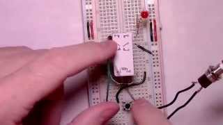
- Video demonstrates the assembly of an LM386 audio amplifier circuit. The LM386 is a great small scale audio amplifier, but selecting and connecting the right combination of resistors and capacitors, routing the numerous ground connections, etc., so that its output sounds even halfway decent is often quite a challenge. This video follows a schematic that I've developed after much trial and error. A professional audio engineer, etc., would likely be able to construct a circuit that sounds even better. I offer this video as a starting point for those interested in the LM386. It provides one with a circuit that at least doesn't start out with a mountain of strange crackles, pops, distortion, RF interference, etc. Definitely let me know if you build the circuit and later discover ways to modify and/or improve it so as to achieve an even better sound quality. I'm always interested in learning from others.
Parts List:
power supply (5V to 15V DC)
100uf capacitor (used for power supply decoupling)
1/8 stereo or mono audio jack (fits standard mp3/mp4 players)
LM386N - 3 (purchase a quality chip from a reputable company)
220 to 1000uf capacitor (between amp output and speaker)
470pf capacitor (used to reduce RF interference)
10uf capacitors (x2) (gain and bypass)
0.1uf capacitors (x3) polyester tends to sound better than ceramic
10 ohm resistor
10K resistor
8 ohm speaker (1 watt minimum)
standard hookup wire
breadboard
---resistors should be rated for at least 1/4 watt (a higher wattage rating is fine)
---capacitors should be rated for 2 to 3 times the amount of voltage one expects them to 'see', e.g., if the circuit is powered with 9V, then one would want to use capacitors rated for 18 or more volts
Audio tracks used in this video were provided royalty free by CZcams. - Jak na to + styl


I can't believe how you made it so clear and simple. Thank you so much great instructor.
Karim Ismail Appreciate the comment and feedback. Glad the video was helpful and thanks for watching!
one of the best explanation on this amp, thanks!
drbonkie Thanks for the feedback, glad the video was helpful.
Great tutorial, even I could easily follow it, plus you explained what and why the the resistors and capacitors do, brilliant!.
Thanks so much!.
Greatly appreciate the comment and feedback. I'm glad the video and explanations were helpful.
Great vid, very detailed explanation and great pace. You're a great teacher!
tb0nestk Appreciate the comment and helpful feedback. Thanks for watching!
I found this video very informative. I'm in an Electronics Engineering program and are working on an audio amplifier circuit for medical workers and law enforcement and this eased a lot of problems I was having with distortion and feedback in previous circuits found on other sites and notes.
+Ryan Lovatt Thanks for the comment and feedback. I'm glad the video was helpful with your project.
Thanks for watching!
Great video. I like the way you took your time and explained step by step. Things like this fascinate me but i don't have the proper education on what most parts mean or are Watching you explain this gave me a basic understanding of most components. Thanks for this video. BACON!!!!!!
edgar ramirez Thanks for the feedback and for watching the video!
I'm especially glad that the video was helpful. There's often much more that could be said and explained during the videos but I always try to include (at least the minimum) of what one might be interested in (or become little confused about, etc.) while building a particular circuit. If you ever have any questions about the functional role of a particular component, why something was included in a circuit, etc., then please let me know in the comments and I will always do my best to help.
Excellent *tutorial.* Very good explination and diagram. Thanks
Appreciate the comment and glad the video was helpful. Please let me know if any questions arise if/when you attempt the circuit. I'll always do my best to help.
To Partho Lad: For some reason I wasn't able to click reply on your comment. No worries, hopefully you'll see this. The 386 tends to work best with an 8 Ohm speaker around 1 to 5 watts. It will function with a 4 ohm but there's a chance that the chip might start to overheat if used for long intervals. Also, the high wattage associated with the speaker you mention means that it's built 'heavier' than, e.g., a 1 to 5 watt one would be. 'Heavier' coil, cone, etc., typically means more work for the chip to do, more work means more strain and more heat. Assuming the chip successfully moves the speaker (which it may be able to do) you could certainly use it to test the circuit. A short test shouldn't hurt anything. But for consistent usage and long intervals I'd try to locate a 8 ohm 1 to 5 watt speaker. Hope these comments help. Please continue to let me know if/when there are any questions. And, thanks for watching.
Hello, I just finished the amplifier. It sounds better than other layouts. Very clear explanation and I could build it although I didn’t know anything about electronics. Thank you so much for your effort and teaching. I'd appreciate if you could teach us how to make it stereo.
thank you so much this video is very informative
Great video, easy to follow, very helpful..... thanks
Nicky Nance Appreciate the comment and feedback. Thank you!
really nice tutorial,simple and very well xplained
Piddy D Appreciate the comment, thank you.
really nice...thanks for this video..
Great video. Thanks a lot!!
brotherlex Appreciate the comment and feedback! Thanks for watching!
nice explanation of schematic.
Great Job. Thnx Man
Very nice and inspiring tutorial for a beginner like me, i hope you could upload more videos and tutorials about circuit assembly, and i wonder if you can teach us how to create a delay guitar effects.. keep up the good work!!! god bless you awesome dude.
jiorgio davis Appreciate the comment. I'll definitely be uploading more circuit assembly videos soon. I'll also research some the various ways one might create such effects and see what I can come up with.
Thanks for this, its works great! I'm using 2x 4Ω speakers from a mini marshall stack and it actually sound a whole lot better than the mashall circuit!
chris Bryson Thanks for the comment and feedback! I'm glad the video and circuit were helpful.
Really helpful thanks :)
Hi Philo Mech, I learned from JohnAudioTech on CZcams, that having separate ground paths for input, output & power that junction right at pin 4, ground, will greatly reduce if not eliminate pops, crackles, etc.. I have had good success using this method. C.
+Cass Virgillo Appreciate the comment and reference to John's channel. I enjoy many of his videos too. His 'star ground' video is certainly helpful and a technique often used in analog signal and amplification applications. I chose to "separate" the speaker vs signal grounds by routing each to different rails of the breadboard in the video. But, for a more finalized circuit board setup using a star ground tends to be my preferred method as well. Hope these remarks are helpful. Thanks for watching!
great vid good clear instructions worked first time chears philo mech
bob up Appreciate the feedback and thanks for watching!
verry helpfull and precise instructions,i am just begining electronics after retireing a few years,and was wondering if this circuit could be used for verry hard of hearing .i look forward to seeing more of your projects,it was verry well explained thank Mike
Mike Hancock Appreciate the comment, feedback, and question. The circuit can certainly be used to amplify audio signals in a variety of interesting and useful applications. And it's great that you're beginning electronics, it's always an enjoyable world to explore and learn more about.
As to the 386's suitability for a hard of hearing application: The chip wasn't designed for usage in medical devices (or as one) and in turn isn't guaranteed, for lack of a better phrase, "to reliably be there when/if one were to desperately need it" (like e.g., while driving a car, crossing a busy intersection, etc.). Hearing assistance tech is typically tested, retested, etc., etc., just to make sure that it will likely (hopefully) "be there when/if needed". This being said, it very well might work, but I can't in good conscience I can't recommend it for such.
However, if the idea was more along the lines of having it serve as the centerpiece to, e.g, an in-house intercom system or perhaps as a headphone driver, then I can say yes to the intercom and maybe to headphones.
I've used it as part of a in-house intercom system, it's greatly reduced the need to yell across the house...turned out to be a very handy thing to have around.
As to the 386 being suitable for headphones: It mainly depends on the type and impedance of the phones. It wouldn't be the best for use with headphones having a impedance higher that 8 ohms. Most of the headphones I've encountered have been 16 to 32 to 64+ ohms. Though it should work in the case of two 16 ohm phones if one rewires them to operate in parallel (in turn reducing the total impedance the amp sees to around 8 ohms). But attempting to use it to drive a typical pair of 64 ohm phones would be too much of a load in the long run...the 386 would do its best to drive the load and might do a decent job of it for a little while but it likely wouldn't do so for long. Audio amps like the 386 will do everything they can to drive the load, regardless if it's outside their tolerance ranges. If the load has way too little or too much impedance, then they can overheat, internally fail, etc.
In the end, the circuit can definitely be used for a huge range of applications and I've found it to be helpful in quite a few unexpected ones. In house intercom, yes. Headphones, maybe. One would need to pay careful attention to the impedance. But, as a substitute for hearing aids or the like, I wouldn't trust it to keep one safe.
Hope these comments are helpful. Thanks for watching the video. And, please let me know if there are more questions. I will always to do my best to help.
Hi Philo, Thanks for the very nice and informative video. Would you be able to do another tutorial video involving the assembly of a simple single tube amplifier? Thanks again.
+Lechon Santos Appreciate the comment and question. I've only worked with a few tube amps. The majority of my experience is with transistors, chip amps, etc (all the post-tube-amp stuff). I have always wanted to take the time to learn more about tube amps and will do so sometime in the future. At the moment I wouldn't want to mislead anyone with a tube amp build. But, as soon as I have the time I will do some research and see if I can come up with something that might be helpful. Hope these comments help. Thanks for watching!
very helpfull. Thankyou.
Robert Tomkinson Thanks for the comment!
thanks,,,clear and sound,.,with all the explanations, i did it,.,.,sounds very good ,,any idea with 2 speakers ???? and bass boost ??,.,
Thanks great video. Had you created something with a bigger wattage?
hey! I've made 4 audio circuits, your video of 386 is the only one to work. thank you very much for taking the time and effort to realize what people do without good explanation. in this circuit ..does the input have to come from a device or would a contact (piezo)mic work? thanks again you do just right
Thanks very much
+Noko Kgomo Thanks for the comment and for watching!
Thank You Man! :)
Marc Paradis Thanks for the comment and for watching!
This is a fantastic video! Thanks for taking the time to produce it! I was wondering, though, if you could be more specific as to the type of capacitors and resistors you're using? I'm new to electronics, and am confused by the different materials, and the voltage ratings. Thank you!
mmassinger Appreciate the comment and question.
1/4 watt (or larger) resistors are fine. And capacitors rated for 2 to 3 times the voltage you expect them to 'see' inside the circuit are fine, e.g., if you powered the circuit with a 9V battery, then you would want to use capacitors rated for 18 or more volts. Hope these comments help. Please let me know if there are more questions and I will always do my best to help.
Thanks for watching!
Firstly, very well explained tutorial for people, particularly those new to audio electronics. I have built a number of LM386 audio amplifiers (as well as others audio amps using opamps). Despite what some say, I have experienced NO noise or distortion, unless the input source volume is set ridiculously high (which the chip does not like) and find it a very good IC. Just a couple of comments which I hope you don't mind. I have never experienced any radio interference on my circuits (breadboarded or soldered up) so I wonder if you live very close to a transmitter? I have never therefore needed a capacitor between pins 6 & 4. I couple pin 2 directly to pin 4 (very short jumper wire) and then put a 1uf capacitor between pins 7 & 4 (with no resistor - not sure why you have a resistor there?). In that way, all the necessary pins are linked to ground with minimal use of extra wire which can introduce noise. I add a 100uf decoupling capacitor from positive to negative rails immediately after battery power terminals. Finally, though I don't know how important this is, I put the low value capacitor/resistor series (from pin 5 to ground) the other way round (i.e capacitor followed by resistor) as indicated in the datasheet . The speaker used is indeed quite important. I have found that I can drive a 8 Ohm 6" speaker rated at 20w with the N1 chip (though not supersonic volume) but on of the best speakers I have used with this setup is an old 3", 8 Ohm 3W Nokia car phone speaker :-) Hope you keep making great videos, encouraging people to build their own stuff. Regards
standishgeezer Appreciate the feedback and the circuit description! I'll certainly try out the design. Interestingly enough, unwanted RF tends to be the norm whenever I build audio amp circuits. I currently live in the middle of a larger city (multiple transmitters just a few blocks away). So, I couldn't get away with leaving out the pf cap on the input line, I often have to add more, as well as some high pass filtering, etc. Jumping a ground over the chip would certainly work, I tend to do the same when I move to protoboard. I routed the grounds as shown in the video for ease of presentation while at the same time holding on to the target (low noise, etc.) functionality. But any routing that reduces wire length is always going to be a plus with an op amp circuit. Decoupling the supply lines is certainly a must, I added two supply line decoupling caps to the board. Adding even a few more likely wouldn't hurt. As to the (perhaps) strange orientation of the low value resistor and cap series, I swapped their ordering solely because it sounded a little better to my ear. Both orientations will work, I simply liked the way the orientation in the video sounded a little better. Agreed about the speaker. I've often been surprised by how much difference a speaker can make. One of two supposedly 'identical' speakers might in fact sound better (at least in my experience). All this being said I definitely appreciate the feedback and that you watched the video. I greatly enjoy making the videos and hope that they help to encourage some to enter the always interesting world of electronics.
Nice video...can you tell me what the bypass at pin 7 does...I disconnected mine and nothing happened...thanks..
Sir I am an old man of 56 and electronics is my hobby and with this fantastic video, I was able to make an audio amplifier for which total credit goes to this video. I have a desire to build a clock with 4 digit seven segment display without aurduino so that I can use it regularly. Sir is there any video on this? If so kindly provide the link as in our country there is very little scope for old man like us. Regards, Satyaban
hey there!!
i"ve got 8ohm, 30 watt speaker
will this schematic do it perfect or i will need some improvements??
Thanx for help :) & offcoarse the Video
I used 47,000uF on the output and it sounds great
The Computer Tech Guy Appreciate the comment and feedback. Glad the video was helpful. Thanks for watching!
Should the ground coming from the power supply and the source be connected together? Have it connected from my phone through a TRRS breakout board. When I connect the source ground and pin 2 to the ground rails I get no audio, if I connect the source ground to pin 2 only it works and I get quite a bit of sound.
can we connect condenser mic as a audio source instead of any other source ?
2:00 sounds like the schematic police are after you lol!
awesome tutorial....can i ask what voltage rating of capacitors you used and the wattage used in the resistors...i really want to do the same thing with what you did , the sound quality is good..keep making awesome tutorials
random modnar Appreciate the question and feedback. Capacitors rated from 16V to 50V & 1/4 to 1/2 watt resistors will work. For,e.g., a 9V supply, caps rated 16+V are fine, for higher supply voltages one might want to move up to caps rated for 25 to even 50V. The general rule of thumb is to select caps that are capable of handling close to double to in some cases triple the voltage one actually expects them to ever see --similar reasoning applies to resistor wattage. It's generally better to select parts capable of withstanding 2 to 3 times the 'stress' they will ever see. Hope these comments help. Please continue to let me know if there are more questions. I'll always do my best to help.
and it works great,
freak55beat Thanks for the comment and feedback. Glad the video was helpful. Thanks for watching!
Great video! I am using an lm386 m-82 ic and a .5 w 8ohm speaker. The speaker is only clear when the volume on the phone is really low, otherwise it gets really fuzzy. The volume does change when i turn the potentiometer, so i'm pretty sure the circuit is hooked up right. Do you think this is because of the speaker or the IC?
Hmm, did not know that Forest Gump is interested in electronics :)
Great vid btw!
This was a wonderful tutorial on how to build this little amp. My first bread board project and it worked! One question. When I first ran it it was so loud I had to turn the potentiometer way down. Then unhooked the speaker and hooked it up again and volume is much reduced. Any ideas about what I might have done?
Never mind. It was just the difference in my phone vol. that I was using for the input. Sorry.
Had much fun doing this. Thanks for posting.
flp2mm Appreciate the comment and glad the video was helpful. I've encountered that unpleasant surprise of way to much volume on power up before as well. It can definitely take one by surprise. I always try to remember to turn the input volume down before powering amplifier circuits, but often forget to do so. You had a nice 'hello audio world' experience with sound. The first time I attempted an audio circuit I had no sound at all and when I did eventually get the amp to do anything it was all obnoxious static and noise. Analog circuitry sometimes acts as though it has a mind of its own...in many ways that's what makes it so much fun to experiment with. Definitely let me know if you have any questions as you attempt more circuits, I'll always do my best to help.
To Noe Flores:
Thanks for the question and for watching the video. I wasn't able to directly reply to your comment through the reply button. Hopefully, you'll be able to see this comment instead.
The capacitors used in the video had a voltage rating of 25V or above. The general rule of thumb is to use capacitors with a value 2 to 3 times higher than the voltage you ever expect them to see during normal circuit operation. For example, if one used a 9V battery to power the circuit, then capacitors with a voltage rating or 18V or higher would be fine. Hope these comments help. Please let me know if/when there are more questions and I will always do my best to help.
philo mech what is the diffrence between using this and a 555 timer?
Owen Chase I'm not quite sure that I understand the question, might you say a little more?
The LM386 amplifies audio signals whereas the 555 timer can be used to perform various timing, bistable, astable, etc., tasks. The chips are for different purposes.
Might I have misunderstood what you were asking? If so, then please let me know and I will continue to do my best to help.
Thanks for watching!
Well I have seen amplifier circuits using the 555 timer.
Owen Chase Aha! Now I understand the question. Yes, it's certainly possible to use the 555 timer as a component in a PWM/Class D style audio amplifier circuit. By itself the timer doesn't source much more that 200mA but if paired with an appropriate mosfet it can be used to make a fairly decent sounding PWM based audio amplifier. Conversely, the 386 is the more traditional Class A/B (analog) variety. Some will claim that PWM based amp circuits tend to not sound quite as nice as analog ones. But, there are certainly some nice sounding PWM-based amps out there. I've always been a little more partial to analog amps, but Class Ds do tend to be more efficient in the long run. But if efficiency isn't really an issue, then choosing between analog vs. PWM based amps is largely a matter of what one happens to prefer. Both will serve to reproduce and amplify audio signals but one or the other will likely sound better or worse depending on who happens to be listening. Also, given the timer's current sourcing limits, one needs a mosfet to bring up the sound to a higher volume whereas adding such isn't needed with 386, 383s, etc. Essentially, two of the core differences between the timer and 386 would seem to be analog vs. digital audio amplification and the need for an extra current sourcing component i.e., power transistor/mosfet, or not. There are more but these are two of the primary ones.
Both types of amplification circuits are enjoyable to build and learn about. And, they're both worth being familiar with.
Hope these comments help. Just let me know if there are more questions and I will continue to do my best to help.
thanks for your time and answering me. I have one more thing to ask, I dont know if you have built a transmitter circuit but these chips take very little current to run, if they take little current to run how do I get the transmitter to run at a couple watts because you cant put that much power through these chips because I want to transmit at a higher wattage?
I have an 8 switch component. Do you think I could try some things with that connected?
hello,, what if i use a 12 volts for power supply,, is there any problem with that,, or there is a part or materials that need to replace?
I have a bluetooth chip as my audio source. Could I connect that directly to pin 3 instead of the Potentiometer? If so, would I still need the 470pf capacitor from pin 3 to ground to isolate rf noise?
On the top left of the diagram,,,the audio IN negative goes to the volume control or variable resister, at the end wire to ground..is this right? In other words the ground and audio in, goes to the same side or end of the VR...or volume control..
Sir, can i use LM324 instead of LM386. LM324 is the only op amp that i have
Assuming that I wanted a 2 channel amplifier, can I just double the circuit and hook up the left audio input for the audio input of the 2nd circuit? Or do you have a 2 channel amp tutorial? Thanks in advance. Liked the video!
+bien laqui Duplicating the circuit for the left channel will work. You could use a speaker for each or attempt to combine the outputs using a mixer circuit. A stereo chip amp video is in the works. It'll likely be a month or two before it appears on the channel but one is on the way. Hope these comments help. Please let me know if there are more questions. Thanks for watching!
Hi and thanks for this excellent tutorial, only a question: I have the Sennheiser hd 595 (don't know if 50 or 120 oh model) for you can i use this circuit for this headphone (changing the speaker with a female jack) ? Or you suggest me another circuit ? The price for headphone amplifier are too high and i try to build a good one for that use.
wawacco Thanks for the comment and question. Headphones tend to have a much higher impedance than the 8 ohm load recommended for the 386. There are quite a few chips in circulation that are specifically designed for headphone applications. I'm not as familiar with the latest headphone amp chips as I probably should be. I'd recommend searching the websites of some of the major chip brands for "headphone amplifier ICs", try e.g., Maxim, Analog devices, Texas Instruments, etc. One or two searches will likely return many of the most recent and popular options. Hope these comments help. Please let me know if there are more questions. I will always do my best to help. Thanks for watching!
Thanks for the awesome tutorial. This was the most descriptive I found anywhere.
I have a question...How much more amplification will I get if I connect this to a npn preamp?What improvement will it make to the output.
Thanks again.
Appreciate the comment, I'm glad the video was helpful.
Adding a preamp stage to the LM386 circuit is definitely possible, I've done so in the past. The circuit built in the video sets the LM386 to its maximum gain of 200 (via the 10uf cap between pins 1 and 8). Any signal fed to the circuit will be amplified x 200. It's possible to lower the 386's gain by adding a resistor in series with that 10uf cap. Such is described in the LM386's datasheet. Whenever I've added a preamp stage I've normally had to reduce the LM386's gain so as to avoid distortion (x200 gain can become a lot when combined with a preamp stage that's, e.g., x50 gain). It's always a matter of adding a preamp stage that boosts the incoming signal to the LM386 which will in turn boost the signal even more --> while at the same time, keeping all the 'boosting' a little below the 386's distortion threshold.
What one can do: Start out by setting the mp3, etc., player's volume fairly low. Build the npn preamp you have in mind and feed its output to the 386's input. Connect the player's output to the preamp/386 combo and see what it sounds like. Starting with a low player volume will protect the speaker and your ears. Slowly increase the volume and see if the signal starts to distort before it reaches the volume you desire. If so, then I would reduce the gain of the 386 in increments, e.g., from 200 to say 175, from 175 to 150, etc., until I ended up as close to the volume I wanted minus any distortion.
Two things to note:
(1) Most of the npn preamps I've built ended up having a low (ish) input impedance. This can be a problem in regards to some music players. Too low of an input impedance can shoulder the player with having to provide too much current. One doesn't normally have to worry about such with op amps, but it can become an issue when using transistors 'in the raw'. If you're unsure about the input impedance provided by your npn preamp stage, then you might consider building the preamp around an op amp instead (they make some really great high input impedance, low distortion, low noise, etc., op amps).
(2) A preamp built from npn (or pnp) transistors can sometimes add quite a bit of noise into the signal depending on the specific components (caps, resistors, etc.) used in its construction. Any noise the preamp adds to the original signal will be amplified (often exponentially so) when it passes though the 386 circuit. It's often quite surprising how much a small amount of preamp noise can make to the eventual signal quality. It's a case of whatever goes into the 386 circuit comes out amplified x200+ (assuming one sticks with the gain setup demonstrated in the video). It's completely possible to amplify the signal so much that one will begin to hear such unwanted things like capacitor charge and discharge cycling (yuck! I've encountered this nasty occurrence quite a few times...nothing makes a great song sound horrible quite as much as hearing constant cap charge/discharge noise over or under-laying it.).
I definitely don't intend for these comments to discourage. I offer them solely as a way to say, Try it. But, be ready to refine, rebuild, etc., the preamp circuit a few times on the way to obtaining the sort of volume and signal clarity that you might want.
As a final remark, I'm planning to do some videos on building a few different preamp circuits in the next few months and would greatly appreciate hearing about how the one you eventually end up with performs. I'm planning to start with op amp based preamps due to the desire to avoid any input impedance issues, but I would definitely like to know if you come up with an npn version that performs well, etc.
Hope these comments are helpful. Please let me know if there are more questions and I will always do my best to help.
Thanks for especially fast and the great input. I'm building one this weekend for a university projects. Will definitely let you know how it goes. Thanks again :)!
Minhaz Mahmood
You're welcome. I look forward to hearing about what you eventually make. I wish you good luck with the project.
philo mech Just noticed that you are planning to build some preamp circuits and wanted to hear from anyone who had already done so. I have built a couple of preamps using TL072 and LM358 (I've even used the LM386 as a preamp for the LM386! - blog.erikzone.co.uk ). The TL072 and LM385 preamps are very impressive with very little, if any noiset. The TL072, in my opinion has the edge in terms of gain but both are good and have a pin-for-pin match so you can swap them about to see which you prefer. The added advantage is that both of these are dual opamps and therefore leave you a free amp to incorporate a simple tone control circuit. Happy to share a schematic (badly done in Eagle - as I'm not great with Eagle) or as a graphic..
standishgeezer Greatly appreciate the comment and link!
I'll make sure to check out the schematic. No worries about Eagle, I can relate. Eagle is nice but the search for the sort of symbol one might want for a given schematic can sometimes be a pain (combing through the libraries, remembering where a desired symbol is located, etc.). If the circuit is of a reasonably small size I tend to manually draw it (as evidenced by all the hand drawn schematics in my videos) rather than use the design software. But the software is certainly handy and often essential when it comes to manufacturing a more polished and tidy circuit board.
I've worked with the TL072 before and was planning to use it in a future preamp video. It's a really nice chip, little to no noticeable noise, etc. It'll likely be a few months before I can construct and upload a preamp video (quite a few viewer requests and personal projects to attend to first) but one (or more) preamp videos is/are definitely in the hopper and on the way.
Thanks for watching!
So I love the audio quality from this amplifier, I've been scouring the internet for a good DIY one, but it is super loud on my 8 ohm 5 watt speaker. I didn't use a 10k potentiometer, could this possibly be the problem? Any help is appreciated!
Appreciate the comment and question. As long as it's possible to adjust the volume level from the mp3, etc., player then the potentiometer is largely redundant and not necessary. However, if the music source doesn't have a volume control, the potentiometer or at least a resistor will be needed for volume control. Assuming you don't have a potentiometer on hand, then I'd encourage you to try placing a 2.2k to 10K resistor in between the music source and amp circuit and see if the volume decreases to a more desirable level. Hope these comments are helpful. Definitely let me know if there are more questions. I'll always do my best to help.
using a 12v motorcycle battery, what would it take to get 10-20 watts output?
Hi, Do you think you would do a tutorial with a TPA3122 stereo chip?
+MonkeyMagic Elecifun Thanks for the comment and question. I haven't done a video on the TPA3122 yet but I will certainly add it to the list of upcoming videos. I'm in the process of moving at the moment and it will be a few weeks before I'm able to add more videos but I will make sure to put the chip on the list. Thanks for watching.
Hello philo mech
Just out of curiosity, can you explain the purpose of the bypass of pin 7.
Orlando Gomez Thanks for the question and for watching.
It helps to reduce power supply noise that might otherwise find its way into the inputs.
The 386 is quite sensitive and will tend to amplify even the slightest power supply ripple, noise, etc. The cap on pin 7 helps to reduce some 'noise', the pF cap on the +input helps to reduce further noise (RF in that case), the 100uf across the supply rails helps to reduce even more noise, and the usage of the shortest wires possible helps to reduce even more noise. In the context of most op amp circuits decoupling caps tend to be one's best friend in the battle against noise.
For further discussion of pin 7 and the reason for decoupling it through a cap one might also check out, e.g.,
www.diystompboxes.com/smfforum/index.php?topic=88334.0
Google keywords: "DIY stompboxes LM386 pin 7 cap"
philo mech- I was reading thru some of the post below and happened to read the one posted to ViTALiY that really caught my eye I plan on building this 386 as well I built one a Long time ago and it still works good but I want to build another one w/SMD to add a Audio in & out for a 7" TFT monitor FPV all in one unit, but back to the Spectrum Analyzer you mentioned in the post below I was a Sound Tech for Live bands Years ago and always had to borrow a room Analyzer to set the EQ on my 32 Band if I had a bad room or had feed back that I just could not get rid of and still sound good- but most of the time I just did a sound check an Hour before the doors opened and that usually worked Jameco Use to sell a 32 band Room Analyzer kit w/LEDs the whole nine yards but they no longer sell it and NO ONE even makes that kit anymore at least I cant find it I think it was made by Velleman? the one your are going to build and post is that similar to the same thing? Sorry this was so long I'm Italian and don't know when to shut up or get to the point sometimes!!!! LOL
Rosario W Appreciate the question and interest in the spectrum analyzer project. The one I was describing to ViTALiY is much more humble than the 32 band you mentioned. It's targeted toward the beginner level, only has a 7 band capacity, 56 leds, etc. It's a project designed to demonstrate how one can build a very basic but nonetheless visually interesting analyzer without having to figure out how to code, e.g., FFT, without relying on special libraries, etc. A project that those somewhat new to the Arduino world could successfully complete with a little patience and perseverance, etc. But I am glad that you reminded me about the 32 band room analyzers. I'm pretty sure that I have one of those kits somewhere in the house. I remember assembling one quite a few years ago and thinking at the time that it would fun to design and build one from the ground up. I can see an enjoyable new project and set of videos on the horizon. Though that will have to remain in stasis for a while longer. I have quite a few to projects to catch up on at the moment and work is always much more time consuming during this time of the year. But a series of videos on how to build a much larger, fancier, and in the end more practically useful, spectrum analyzer sometime in the future, definitely.
I'd like to hear more about the TFT monitor, etc., project as you make progress on it. I always enjoy hearing about what others come up with, learning what they discover along the way, etc.
Thanks for watching and please continue to let me know if/when there are any questions, etc. I'll always do my best to reply in a timely manner and offer any help if it's ever needed.
Philo mech, Thanks for the getting back to me and the all the info. Count me in on the spectrum analyzer! when you get around to doing it. I understand how busy things can get and that's no easy project either. I have always wanted one or to build one I don't know if I mentioned it but I'm self taught and have a lot to learn and a long way to go but my hobbies seem to change as the seasons do around here in NE Ohio lol in winter time its Electronics, R/C Drones, Helis & Pyrotechnics (I'm also a licensed shooter class A&B) then spring and summer is the time to try out all the stuff I tried to build in the winter (Pyro shells too) I'll keep a eye on your channel and subscribe. As far as the TFT FPV set up I would be glad to share that with you and let you know how its going or more likely NOT going lol maybe I could run a few questions by you if I get stuck? I'm waiting on a very small Video Rx board in the 5.8Mhz band from BangGood.
I already have and built the Tx w/camera for in flight video If you run across that Room Analyzer kit and think you might want to sell it keep me in mind I know when Jameco sold it in kit form it was around $99 I think? Thanks again
Rosario W My apologies for the delayed reply. I can definitely appreciate having multiple interests and hobbies. My interests stretch from mechanics to electronics to philosophy of mind and the cognitive sciences to name just a few. I'll gladly do my best to help if questions arise during the TFT project, just let me know. I'm still looking for the analyzer kit...I'm certain that I didn't throw it out...but I'm beginning to suspect that I might have loaned it to someone...which often means I unknowingly "gave it away". If I find it, I'll definitely let me know.
Hi, love your work, you explain everything pretty clear. I have one question: Could I use a bigger speaker, i mean a really bigger speaker.
Thank you
Thanks for the comment and question. Glad the videos are helpful. As to using the LM386-N3 or N4 to drive 'larger' speakers: The chip will only (safely) output about 3/4 (N3) to 1 (N4) watt of overall power. That's not a whole lot when confronted with a speaker capable of handling, e.g., 5 or more watts. Every aspect of higher wattage speakers is built (for lack of a better word) "heavier". An analogy is often helpful: Suppose one tried to push a bus up a hill with a scooter. The scooter might rock the bus a little but there's not much chance of it actually pushing it up the hill. And perhaps more importantly, what happens to the scooter during such an attempt? It would try its best, likely hurting itself in the process, with the end result being an injured scooter and an unmoved van. Likewise, hooking the LM386 up to a larger wattage speaker would likely result in it trying its best to move all those "heavier" speaker parts with little success and possibly injuring itself in the process. A very little speaker movement (and in turn sound) might be emitted but not enough to justify the strain being placed on the chip. It's not always necessary to match amp wattage to speaker wattage, in fact having speakers a little above an amp's operational wattage is often perfectly okay. But very large differences in either direction are not good (amp that sources a lot of watts hooked up to a tiny speaker = volume goes up then huge distortion and likely injured speaker --or tiny amp sourcing tiny watts paired with big heavy speaker = strained and potentially injured amp...I say possibly here because some amps include forms of internal over-current, etc., protection). In the end, if one wants or needs to drive higher wattage speakers, then I'd encourage looking for an amp with more wattage capabilities than the 386. Hope these comments help. Definitely let me know if there are more questions. I'll always do my best to help.
is the most important part the capacitor on the gain? every other capacitor reduces the noise right? i cant get my head around why there are so many capacitors and what values to use
+Sunny Appreciate the question. The gain capacitor is important, one can add a potentiometer in series with it and have an easily adjustable gain. I tend to run all of my 386 circuits at max gain with the 10uf and adjust the value via the 10K pot on the input line or by the music player. The capacitors in series with the input and output lines are used to prevent DC voltage from entering the amplifier. Each of the other caps, the' 470pf input pin, 10uf bypass pin and 0.1uf on the output line are used to reduce noise. 386 circuits tend to be cases of constantly striving to reduce as much noise as possible. There are many other audio amp chips where the number of capacitors can be greatly reduced, for a good sounding stereo amp chip that doesn't require tons of external caps one might check out the LM4752T. Hope these comments help. Please let me know if there are more questions, etc., and I will always o my best to help. Thanks for watching!
Hi! Good video! But I've built the exact same circuit and I get a LOT of distortion, so my question if it can be related to the 9v battery I'm using (currently is giving me 8v) or the speaker. The speaker says that it is a 8 ohm 2w, but do you think changing the speaker would make any difference? Thanks
Adrián Rodrigo Guitar Appreciate the comment and question. The battery is likely not the cause. The speaker might be a contributing factor but it's most likely the 386 or one of the additional components. First, does the chip have corporate markings, e.g.,Texas Instruments, etc.? If not, then you may have acquired one of the many aftermarket knocks offs. I've never had much luck with non-branded chips. They most always sound quite horrible due to poor manufacturing. If you do happen to be using a chip made by one of the major companies, then the chip is likely fine and the distortion is entering either through the wires, capacitors, resistors, or potentiometer. A systematic search is the best way to locate the possible cause/s. Assuming the chip is good, then I would first swap the potentiometer with another one of the same value. Turn the knob back and forth and see if the noise decreases. If so, then you'll know the potentiometer was partly the cause. Next, swap each component in turn for one of the same value. It's quite common for one potentiometer, resistor, capacitor, etc., to sound a little better than another of the same value. I often test 5 or more of the same component in an audio circuit until I find the ones that sound the best (i.e., the ones that introduce the least amount of noise into the circuit) Also, did you keep the wires as short as possible? Any added wire length can add noise to the circuit. Hope these comments are helpful and point you in the direction of locating the possible cause/s. Definitely let me know if there are more questions, etc., and I will continue to do my best to help.
Thanks for watching!
philo mech Hi! Thanks for the reply. It's not definetely the lm386, it is a good one (National Semiconductor). I will try to replace the pot because I think it's pretty cheap and horrible. The problem however it's not the static noise, it's the massive distortion when you turn up the volume a bit. I've done the circuit in a small PCB with bridge wire and stuff like that and very close to the chip. Must be the pot or some of the capacitors as you said. Thanks for helping!
Adrián Rodrigo Guitar Thanks for the reply. Having eliminated the chip and wires, all that remains are the pot or caps. ...Or, it might be that the gain is a little too much for the signal being sent through the circuit. The gain was set to max (200) in the circuit described in the video. It's possible to lower/reduce the gain by adding a resistor in series with the 10uf cap across pins 1 and 8. If changing the pot, caps, etc., doesn't remove the distortion, then I'd try reducing the gain. Start by removing the 10uf cap between pins 1 and 8, and see if the volume is still enough for your application. If so, then all is well. If you would like for it to be a little louder (but not to the point of distortion), then try adding a 10K resistor in series with the 10uf cap between pins 1 and 8. The 386's datasheet discusses how specific resistor values in series with that cap will effect the gain. For fully adjustable gain one can add two legs of a potentiometer (10k would be fine) in series with the 10uf cap. Hope these comments help. Please let me know if there are more questions and I will continue to do my best to help.
I have a comment...on the ceramic capacitors..you have a + sign by them..and I think some beginners will think that is an electrolytic capacitor when it is a ceramic with no polarity..Nice video by the way...
+Kennynva T. Appreciate the comment and feedback. I thought about omitting the polarity symbols for the ceramic caps but decided to include them just in case someone attempted to use tantalums instead of ceramics. Tantalums can misbehave (i.e., fire) if inserted backwards and erring on the side of caution at the risk of a little confusion seemed to be the better course. Hope these comments help. Thanks for watching!
Oh ok..I'm old school...and used only ceramic back in the day...thank you very much...Hey what would happen if you took the output of this circuit and connected it to the input of a complete other circuit..???
sir what value of resistors you used to convert stereo cable to mono..thnxx for such a wonderful video
Thanks for the question. In the video I just used one of the two stereo cables, no resistors. Most of the stereo to mono demonstrations that I've seen use 10K to 100k resistors. I'd start with 10K and increase/reduce as needed. Hope these comments help.
Thnxx for your quick and valuable reply.. God bless u
I was wondering how long it would take you to realize the ground wasn't connected.
This one of great DIY using lm386. I have watch your video and recommended to my friends.
Although I have some questions to address, would be very appreciate if you replied to me too thanks.
I am now on a project to build a PA System. 1st question I wanted to address is the wattage of speaker and its Impedance. I am looking to use an 4ohm and higher than 5watts speaker roughly around 50watts as I have an spare car speakers. Using your schematic and components value, would this be suffiecient tp drive the speaker and produce a decent amount of audio signal?
2ndly will it be possible to add a 3way active crossover to this circuit?
And 3rdly is the resistor-capacitor, on the output of your lm386 (pin5) was tp calculate the gain of an non-inverting amplifier?
Would be really glad if you can help me answer my queries. I'm really glad to saw all your comments and reply on your videos!! Please continue to build such DOY's!! Thanksss
Rodulf Ramos Appreciate the comment and questions.
1) A 4 ohm speaker will make the 386 source more current than an 8 ohm. I've used the 386 with 4 ohm speakers without problems. But, doing so tends to make the 386 run a little warmer than usual (it depends on how much volume is desired, consistently low volume --no problem, consistently high volume ---potential overheating problem). If the chip becomes too hot to touch, then adding some form of heat sinking will be necessary. In the end, a 4 ohm speaker will likely work as long as some form of heat sinking is included if/when needed and the volume isn't consistently set too high.
The 50 watt speaker rating is of greater concern. The 386 might be able to move the 'heavier' cone of a speaker with that wattage but I suspect that it won't do so very well or for very long.
If it is able to move it enough to produce sound, then the sound likely won't be very loud. And, the chip will be doing its best to move it. Which means that it will being straining and that might result in too much heat for the chip to safely handle. You can certainly try it and see what happens. The worse results will be: 1) no sound, 2) sound but at too low a volume to be usable, or 3) decent volume but an overheated 386. Essentially, attempting to use a high wattage speaker might produce unwanted results. The 4 ohm impedance will already be causing the chip to source significant current and that combined with its efforts to move a speaker with a 'heavier' cone will likely result in an overheated chip even after heat sinking is added. If you decide to try it, I would definitely closely and repeatedly check the chip temperature after a few seconds, minutes, etc. I would want to be sure that it's not a fire hazard. More than likely, the chip would stop functioning prior to melting, catching on fire, etc. But, I wouldn't want to assume such. If you decide to try it, then I would encourage careful attention being paid to the chip's temperature. Operate the circuit at the maximum volume you ever expect to use for a few seconds, minutes, etc., and check the chip's temperature (across multiple iterations). If it seems to repeatedly reach an undesirable temperature, then another amp chip will likely be needed.
2) It's definitely possible to add a 3 way active or passive crossover to the circuit. Just add one between the chip's output and the high, mid, and low speakers. Though it's worth noting that this is a -mono- circuit and depending on the song, some frequencies may not be present on the output due to being sent out the unused left/right input wire (the line not connected to the chip's input).
3) The low value resistor/capacitor network included on the chip's output line ahead of the speaker is serving to remove any ('super') high frequencies that may enter and be amplified by the chip.
Hope these comments are helpful. Please let me know if there are more questions. I will always do my best to help. Thanks for watching!
philo mech thanks you for your very efficient reply.
So Now I have decided to get a speaker rated at 8ohm 10watt. But It has an maximum wattage of 30watts.
Taljing about the IC lm386. How would I possibly calculate the power on the output. Lets say I have an input of 10v.
With the use of 10uf for the gain. As you have told It Is in maximum gain which I think is 200 for lm386. Am I cprrect to say that?
Rodulf Ramos Thanks for the reply and questions.
Calculating the power output at 10V is possible but such will only reveal 'ideal' numbers rather than what is actually being delivered by the specific chip one happens to be using.
Performing the tests described in the the following two videos are how to determine what the supply voltage vs. power output actually is.
Channel: JohnAudioTech
Video title: Audio Amplifier Supply Voltage vs. Output Power
czcams.com/video/mdL2cVq-VFM/video.html
Channel: Sonic Electronix
Title: How to Calculate Amplifier Efficiency
czcams.com/video/APztzyv0xBs/video.html
Connecting a 10uf capacitor across pins 1 and 8 provides a gain of 200.
Hope these comments and the linked videos help. Please continue to let me know if/when there are questions and I will always do my best to help.
philo mech thanks for the links. totally got what i was looking for! cheers!!
on the other hand. could i possibly get your email add?
Rodulf Ramos Glad the video links were helpful! You can email to me via the private message link on the About page of this channel. Please continue to let me know if/when there are any questions, etc., and I will always do my best to help.
Thanx for the great vid philo mech! I have found only your video explaining this circuit as good. I have some big questions though-
1) I dont have the 470pf capacitor at pin 3. I have 100n, 10n,1n, 1pf, 10pf and 22pf only. I also have a trimmer capacitor with a range 5-50pf. Is there any way i could combine these to make a 470pf?
2) Is that 10 ohm resistor really necessary? I cant find it i have a 51 ohm resistor will it work with that?
3) My lm386 has LM386 L written on it. Will it work?
4) Can this circuit accommodate an electret mic at the input? If not, what modifications need to be made?
Please help.
Advait
Advait Mehla Appreciate the feedback and questions.
1) Instead of combining the caps I would suggest substituting the the 1nf for the 470pf, 1nf should serve to cancel most RF noise (if any happens to be present).
2) the 10 ohm resistor combined with the capacitor serves to remove the last little bit of noise before the output reaches the speaker. 51 ohm will work, it won't remove as much noise as the 10 but having any version of that R/C network ahead of the speaker is better than no network.
3) Yes, the circuit will work for the L version. L tends to refer to a lower voltage version of the chip. Just to be safe, check the datasheet and make sure that your power supply is within the chip's acceptable range of operating voltage.
4) Yes. It can be used with an electret mic, though it may not be especially loud without adding some preamp circuitry between the mic and 386.
Hope these comments help. Please let me know if there are more questions and I will continue to do my best to help.
Thanks for watching!
philo mech Thanks for all the help! I will make this circuit in a few days and will surely let you know if i face any problems:)
Advait Mehla Hello again! I have made this circuit but it is not working for some reason. I do not know if the chip is functional bcoz i hv only one of that available with me and this is my first circuit using it. I also suspect my potentiometer(again, its the only one i have) is not working properly and also it isn't breadboard mount and i need to connect wires to the breadboard(who likes that?). Could you suggest any resistor(s) to replace the pot? Also mention how to connect it/them and other troubleshooting tips. Also there seems to be no current across the speaker(i metered the output and there was no voltage reading. Do suggest some troubleshooting tips.
Thanks in advance.
Advait
hi
from pin 6 to 4 is it 1uf or 0.1uf ?
great video you are easy to learn from
MonkeyMagic Elecifun Appreciate the comment and question. It's a 0.1uf. Thanks for watching!
I used 100nF which is the same.I watch lots of these video's, learning. Yours is great, easy to understand from start to finish. I appreciate that. Could I ask another question?
I have a ticking when no sound is being played, faint but audible?
Also, I don't suppose you have done another step by step with a LM1875 ?
+MonkeyMagic Elecifun Thanks for the questions. My apologies for the delay in replying. I'm in the process of moving and it's taking a while to get back to comments. As to the ticking sound, you might be hearing one of the capacitors. A quick test would be to remove and replace each of the capacitors you're current using one at a time and see if the tick goes away. That's where I would start. If the ticking remains, then let me know and we can go from there. I haven't yet done a video on the 1875 but I have a couple on hand and was considering making a tutorial about them. They tend to be quite easy to work with and always sound reasonably good. If you'd be interested in a video about building a circuit around the 1875 just let me know and I will make sure to add it to the list of upcoming videos. Thanks for watching!
Thank you, Its really good of you for getting back to me.
A video around the LM1875 would be great I have two of those chips and wondered if i could make a stereo amp for my work bench. I also have a schematic for a mono circuit but am not sure of what types of capacitors to use. Before I read this, I played around with the LM386 circuit I had built and think I damaged it, something started to smell that your doing something wrong to your circuit smell, oopps!. I have another couple of LM386's being delivered today (44p each) so I will study and rebuild the circuit and hopefully get it to work again.
Hope your move goes well and thank you again. Simon
Nice tutorial, I'm wondering why your ceramic and poly caps are displayed as being polarized in the schematic?
Jake P Appreciate the question. That was done for those who might attempt to use electrolytics or tantalums instead of ceramic or poly. It's rare (in my experience) to see electrolytics in those sizes but they do make them in tantalum. And, some might not have the values in ceramics or polys and think, 'oh, I'll just put this slightly larger electrolytic or tantalum of the same value in their place'(without thinking about polarity). I was guilty of such when I first started out and ended up with a few exploding electrolytics and tantalums. I'd rather be overly explicit at times than risk someone retracing my early days and have an electrolytic or tantalum explode in his/her face. But, you're right, ceramics and polys are normally not polarized and labeling them as such could be a little confusing. But, hopefully now that you've asked the question, we've taken care of any future confusion caused by my choice to label them that way in the schematic. Hope these comments are helpful. And definitely continue to let me know if/when there are any questions. I'll always do my best to help.
Thanks for the quick reply, I like the channel, subscribed. Have you tried any of the Burr Brown Opus opamps?
Jake P Appreciate the subscription! I've worked with a few of them but it's been a while. The one's I have used always worked well.
Does the volume go all the way to 0? Will this work with +-5V input? How could I adjust the output to make it go to both headphone speakers?
+Robert Maurer Thanks for the comment and questions. Turning the potentiometer all the way in one direction will tend to reduce the volume to a near inaudible level. Yes, I've used 386's all the way down to around 4 volts but the volume tends to be much lower. The 386 is a mono type amplifier ic, meaning that a single IC will only amplify (when built as discussed in the video) either the left or right channel from an audio player. Whatever happens to be on the unused channel is lost. But, one could build two of these circuits (one for each channel, one for left and one for right) and then combine their outputs at a single audio jack socket i.e., one output connected to the tip part of the socket; the other connect to the ring part of the socket; while both grounds are connected to the sleeve part of the socket). Such would "unify" the output from both circuits to a single headphone jack socket. However, one would need to be careful about the impedance of the headphones. The 386 wasn't designed to drive much more than 4 to 8 ohm loads (whereas many headphones might be upwards of 60+ ohms). Hope these comments help.
Thanks for watching!
what does the pot do in this circuit? are you just using it as a variable resistor?
Nick Foggia Appreciate the question. Yes, it's used as a variable resistor, nothing more. Thanks for watching!
Can i use this circuit for 100 W 4Ohm speaker
Hello again! Your schematic shows a .1uF cap between pins 4 and 6 of the chip, and again coming off pin 5, after the 10 ohm resistor. But, in your description (voiceover), you say you're putting a 1uF cap across pins 4 and 6, and then regarding pin 5, you say it's a .1uF cap, then you say it's a 1uF cap, and then you call it a 10uF cap. Can you confirm which value it's supposed to be? Thank you!
+mmassinger it is a 0.1uF
Hello. What would be the causes of not hearing anything? Thanks for your video.
Found it. Speaker was melted inside from my slow soldering haha! Although now there's another problem. The audio sounds good but it doesn't seem to be as loud as yours! Thanks again :D
Pedro Ferreira Thanks for the questions. There are a few things to check: 1) Does the volume change when you turn the potentiometer left or right? If so, but the sound is still not as loud as you'd expect, then 2) are you using an LM386 - N3 or N4? If you happen to be using a N1 or N2, then the overall volume capability of the circuit will be less, the N1 and N2 can't source as much amperage as an N3 or N4. Less amperage = less ability to move the speaker's coil. Or, 3) is your speaker 8 ohms and around 1 to 3 watts capable? If it's, e.g., 16 ohms or 5+ watts capable, then the end result will be a lower/quieter overall sound output (due to either case involving more for the current/voltage to "move", more to "move" = lower volume capability in the end). Hope these comments are helpful toward determining what might be going on. Definitely let me know if there are more questions and I'll continue to do my best to help.
Hii,
Is it possible to add a heat sink to the IC to prevent it from heating ????
+VIVEK KUMAR Sharma Thanks for the question. One could adhere a heatsink to the top of the chip with thermal compound and/or locate the chip under a small CPU fan (though not so close that the EMF from the fan is picked up and amplified by the circuit). During most applications the chip shouldn't get too hot. Hope these comments help. Please continue to let me know when there are questions and I will always do my best to help. Thanks for watching!
hello..can I use 12v power for the project? please reply how to make it into 12v power...that's helps me a lot...thanks
+Herdan Lee Appreciate the question. The circuit should work fine with 12V, nothing would need to be changed. Just make sure that your capacitors are rated for at least 16V, a 25V rating would be even better, it's standard to use capacitors, resistors, etc., rated for at least twice the amount of voltage you expect them to "see" during operation ). Hope these comments help. Please let me know if there are more questions. Thanks for watching!
Hi, if i connect an headphone with an impedance of 16 Ohm, i have to change something in the circuit?
Thanks.
Appreciate the question. You can use the circuit to drive a 16 ohm headphone. However, the output power, volume, etc., will likely decrease and there's a chance such may eventually strain the (internal) output stage of the amp. A LM386-N3 was used in the video, I'd suggest using a LM386-N4 instead. The datasheet indicates that a LM386-N4 is able to safely drive up to a 32 ohm speaker at 16V. Using an N4 should give you plenty of overhead to safely drive the headphone at 9, 10, 12, etc., volts. Hope these comments help.
have you thought of doing a teaching corse for beginers, the way you explane the sircuits is realy great 4 old beginner like me??
Mike Hancock Appreciate the question. I've definitely thought about constructing a series of beginner course videos. Having the time to do so has always been the issue. But, I should have much more free time in about 3 months. Might there be specific topics, circuits, etc., that you would be especially interested in? If so, please let me know and I will certainly see what I can come up with.
If I were to use the LM386 to make an Ultrasonic Varmint Blaster, the noise filtered out by your methodology would actually be an advantage. Therefore, what would I do to increase the noise?
Clayton Benignus Neat application! Removing the noise from a 386 circuit is often the challenge. Getting as much noise as possible to enter into the circuit definitely shouldn't be a problem. Remove the 470pf cap on the input side, the cap/resistor pair connected to the bypass pin, and the final cap/resistor network just ahead of the speaker cap. That should allow quite a bit of noise to enter the circuit. If more noise is needed, then the barebones application circuit presented in the 386's datasheet might be even better. If you happen to make a video of the blaster in action, I'd definitely appreciate a link to it. Hope these comments help. Thanks for watching!
Clayton Benignus Definitely a great project and appreciate the detailed description! After building it I'd have to set up a game/night vision camera. Seeing how the unwanted animals respond when it sounds off would be a must (my curiosity would have to be sated) . I like that it deters rather than harms the creatures. It will likely be much more effective than the aluminum cans rattling in the breeze that I often used to deter the deer away from the garden (note that the rabbits merely laughed at the cans while continuing to eat the lettuce). All the parts you mention should be able to produce the effect you're after. But if the 386 circuitry keeps filtering out the higher frequency, then you might try using the timer's output to drive a mosfet to the tweeter. A timer/mosfet combo can be made into a reasonably decent class-D type amplifier circuit. Just a thought.
I always welcome any opportunity to help. Please let me know if there are any difficulties you think I might be able to help with. If you prefer,and rather than using this comment feed, we can discuss such through the private message system located at the bottom of the about page on this channel. Either way works for me.
No worries about the skill level, we all start from where ever we currently happen to be and then learn what's needed along the way. I'm no where near being an 'expert' in all things electronic or mechanical. I'm familiar with many circuits, etc., but there are also domains well outside of my current skill set, detailed RF circuitry being one of them. I let those much more familiar with such than me build and test those kinds of circuits (I simply hack out or purchase RF, etc., modules as projects require them). You'll acquire whatever experience you need during the course of completing the project --- ---that's always one of the most enjoyable parts (at least to me).
I look forward to hearing more about the project as you continue to make progress.
i would like to replace the potentiometer with a resistor. i set the volume of my computer all the way up, then adjusted the potentiometer to where it was loud but with no distortion and measured the resistance of the pot. however, when i inserted the correct value resistor between input of the pot to the capacitor between the pot and the ic, and removed the pot. it was horrible audio.. it was very gainy at low volumes like if the pot was turned all the way up... what would you recommend as a good value if i wanted to remove the pot from the circuit? awesome sound quality btw thank you!
sam davidson Greatly appreciate the comment and question.
I suspect that the noise issue is the result of the resistor's type/composition rather than its ohm value. Especially since the pot produced good sound while the same value resistor produced bad.
Some types of resistors can add noise (and/or inductance if one happened to use a wire wound resistor) to the signal ...the smallest amount of signal noise can sound quite bad once fed through and exits an amplifier.
There's a lot of debate about which type/composition of resistor is the "best" for audio applications. Some tend to dislike standard carbon based resistors and to prefer metal foil types. I've tried both and have had good and not so good luck with both. Sometimes a carbon based resistor will sound perfectly fine, whereas at others it will sound like someone dumped a heap of rocks in the signal. Same goes for metal foil (not to mention that supposed "audio quality" metal foil resistors can be quite expensive, especially if/when they don't entirely alleviate noise problems).
In your case, I'd try swapping the first resistor you tried with another of the same ohm value. You might discover that a different but supposed the "same" resistor might produce better sound (less noise, etc.). This is what I tend to do. There have been times when I've gone through 5 to 10 of the supposedly "same" resistors before finding one that was acceptable. It's certainly worth a try.
Also, if the resistor you initially tried was, e.g., 1/8 watt, then you might try one with 1/4 to 1/2 watt rating. Assuming you have 10 or so of the "same" resistors on hand, it's likely that you will find one or more that won't introduce too much noise into the circuit (or at least less than the first one you tried).
If you don't come across one within your current supply that results in a decent sound quality, then you might try resistors of the same type (e.g., carbon composition or film) from a different manufacturer, or you could try resistors of a completely different type (e.g., metal foil if you initially tried carbon).
Of all the types of resistors, I'd steer clear of wire wound in the context of an audio application due to their tendency to produce a significant amount of unwanted inductance in the line.
I wish I could offer an instant fix, but trying out a few of the "same" resistors one at a time in search of a "good" sounding one, or trying resistors of a different composition/type is often the normal course action. All resistors and potentiometers are definitely not created and/or manufactured equally (note the 1% to 5% to 20+% variance indicated by the silver, gold, etc., color bands...manufacturers know that each 10K resistor they produce is more often than not, not going to be exactly 10K, nor is the internal composition of two 10Ks out of the same batch likely to be exactly the same). Such doesn't matter for many applications, but when working in the domain of audio (and analog signals in general), the slightest granules in a resistor's internal composition can lead to significant noise further down the line.
Fortunately, all is not lost. If all else fails, you can always return to using the potentiometer. But, with a little luck, you'll find a resistor among your stockpile that'll sound significantly better than the first one you tried (I rejected 2 of supposedly the "same" 10K pots before settling on the one used in the video).
Hope these comments are helpful. Definitely let me know if there are more questions and I'll continue to do my best to help.
philo mech Ok, so i got a different potentiometer. Then I soldered everything to a board. First I got everything working and it was really clean and quiet because i didnt hook up the gain yet. Then I put the capacitor between pins 1 & 8. now there is a very faint squeal as the volume increases and is not present if the song is on pause/ audio unplugged. The only capacitor I had laying around was a 100 uf instead of the 10uf that you showed. do you think the squealing is from the capacitor being too big? Also if i touch the output of the potentometer it hums fairly loudly is that normal? I have another polyester capacitor but I'm not sure if that would be too small. Any suggestions? Thanks again!
P.S. i tried a different resistor of the same size and it fixed the noise problem. But, me being indecisive just chose to get a different potentiometer so i would still have some adjustment on the board.
philo mech Ok nevermind! I read some of the other comments and switched power supplies. I had a 12v 1 amp one that I stole from my old router. I switched to the one I got for a recent project which is 12v 5000ma and the problem dissapeared! It also has a LOT more top end it was getting pretty distorted above 2/3 power now its crystal clean! Thanks again!
Nicole Simmons Glad to hear about the success in securing the sound you were after. 386 circuits are (in)famous for being sensitive to a wide and sometimes completely unexpected range of things (they might sound tremendously better with one power supply rather than another, one resistor rather than another, etc.). They can be quite finicky to say the least. Thanks for adding the steps you took to diagnose and alleviate what you encountered to the board. It's always helpful to have access to how someone else reasoned through difficulties. Please continue to let me know if/when there are any questions and I will always do my best to help.
Haha just noticed that I was using my wife's account. All of the replys came from me.lol. I am currently using your circuit in a project I am doing. I plan on doing a video on it once I am finished with it. If you want I will post a link to it in the comments! Thanks again
When I am trying to set this all up, the LM386N becomes very hot (You can get seriously burnt on it). It all seems like yours. But I do not have the thing you put after the capacitor, is this anything needed for this? Everything else seems like yours. I'm a student and I chose this because it all looks cool, but my grades will fall if I don't make this work. Please reply.
EDIT: Now I did put the .1 micro infront of the first placed capactitor. But this time my battery ran hot.. Something is wrong, and I can't find out what.
EᴢʀᴇᴀʟFX | Jᴜsᴛ ᴀɴᴏᴛʜᴇʀ ᴅᴇsɪɢɴᴇʀ Appreciate the question. I'll do my best to help.
What you're describing sounds exactly like there's a short to ground present somewhere on the board.
Some things to check:
1) Was the chip inserted into the board in the proper orientation? That is, did you insert it with small dot and/or scallop in the direction of the potentiometer? If not, then that will be the problem, such would mean that the ground connections are receiving VCC and the VCC connections are receiving ground. That would certainly cause the sort of behavior you're describing so definitely make sure that the chip is properly oriented in the board first.
2) Assuming the chip was properly oriented, I would next suggest re-tracing each of the wires you've connected to the VCC and ground rails. Might one of them have been misplaced while you were assembling the circuit? (might a wire that was intended for the VCC rail have ended up in the ground rail, etc...such is very easy to accidentally do).
3) Assuming all the 'rail' wires ended up where they were intended to go, I -very very- briefly reconnect and disconnect the battery and then feel each of the wires. If one wire tends to be warmer than all the rest, then you'll know that the problem is associated with that wire, and that would help to home in on the source of the problem.
If you perform 1-3 and the problem is not discovered, then just let me know and we will go from there. Note that if 1) happened to be the problem i.e., the chip was oriented 'upside down', then the chip might have been internally damaged during those moments when it was hot. You might have to replace it before the circuit will work. 386's are fairly durable chips, but even a brief short to ground across the entire chip could have resulted in internal damage.
Hope these comments help. Please let me know if there are more questions, etc. I will always do my best to help.
Hello, if I was to change the audio input jack to a guitar input would this circuit still work? Also if I add a potentiometer between pins 1 and 8 would that give me variable gain?
Sam Harries Thanks for the questions.
Using a guitar as the input source should be okay. I've seen many examples of people using the LM386 as a simple and portable instrument amp. I've not personally used this specific circuit for such (don't have a guitar, etc.) but it should work fine for such an application.
A potentiometer placed in series with the capacitor between pins 1 and 8 would provide you with variable/adjustable gain. I thought about adding such to the circuit in video, but for demonstration purposes chose to lean on the side of simplicity (i.e., max out the gain and do volume control through the pot on the input side). But you can definitely have both by adding that second pot.
Hope these comments are helpful. Please let me know if there are more questions. I'll always do my best to help.
philo mech I just want to say you've been a great help, with both your video and your reply to my questions. Thank you! I have another question I'd like to ask. I don't know if its possible with this circuit but if it is, how could I add photometers to this circuit to have variable bass / treble control?
Sam Harries Glad the reply was helpful. It's possible to adjust the bass response of the 386 by adding a resistor and capacitor in series between pins 1 and 5. The datasheet shows a generic schematic for such in the applications section. I've tried variations of the datasheet's suggestions and haven't achieved the greatest quality of sound at the output (this doesn't mean such isn't possible, just that I haven't yet be able to do so to my satisfaction).
Instead of trying to adjust bass, etc., via adding more components around a single 386 circuit you might instead consider adding adjustable filtration circuitry ahead of the 386 (or even a few 386s).
For example, one might try adding an active high pass filter (what might be referred to as an 'active high pass filter 'preamp') in front of one 386 circuit for treble, an active low pass filter 'preamp' in front of a 2nd 386 circuit for bass, and an active midrange bandwidth filter 'preamp' in front of a 3rd 386 circuit for mids. This type of setup should enable one to place potentiometers immediately before or after the 'filter preamps' and in turn enable one to manually adjust the output amounts of each. Now, such would imply that one is also driving a tweeter ('high freq speaker') from the 1st circuit, a woofer (low freq) from the second,and perhaps a full to mid range speaker from the 3rd. One should only need to use one audio input but break it across 3 active filters into 3 LM386 amp circuits out to 3 speakers. This is likely far from an 'ideal' setup in that it would still only be mono, and input impedance could become a problem depending on the design of the active preamp circuitry, but it might provide one with near total control over the amount of presence of each frequency at the eventual output end. Once again, not 'ideal', but possibly doable and definitely an interesting experiment to try....I'm curious about the viability of such a setup and might try it in the next few days just to see/hear what happens. It might result in success, failure, or mediocre sound but it's the fact that I'm not completely sure about the outcome that makes such an experiment interesting and fun (at least for me).
Hope these comments are helpful. Please continue to let me know if there are more questions. I'll always do my best to help.
If I don't have a LM386 audio anmplifier is any other I can use? in the same circuit.
+Rolly C Thanks for the comment and question. The circuit was designed around the pinout, requirements, etc., of the 386. It's not likely to be a direct fit for other audio ICs. But the noise handling techniques are transferable to the construction of most audio IC circuits. The 386 tends to need a more significant amount of noise handling that some chips but I've rarely encountered one that didn't benefit from some external components, a careful grounding layout, etc. If you have a particular IC that you would like to use in mind, then please let me know and I will add it to the list of upcoming videos. Hope these comments help. Thanks for watching!
how complicated can it get if I want to make it stereo? can i just redo all the circuit twice and conect the other cable of the mp3 jack? or is there a better way?.
ps. sorry for the lack of knowledge, just started to learn about this stuff. ;)
Appreciate the comment. Glad you're entering the world of electronics. There are tons of interesting circuits to build and learn about.
Running the right and left lines through their own LM386 circuits will work fine, just make sure to connect the player's ground wire to both circuits --> add a Y to the end of the ground wire and run one leg to the first circuit and the other to the second. One of the player's output lines will tend to carry more of the music (either the right or the left, relative to the song), that's normal for stereo. Definitely let me know if there are more questions and I will always do my best to help.
Thanks
i accidentally bought a 0.1 uf 100vdc radial capacitor. it looks to be quite a bit larger than the ones you are using. Will that work? Thanks! :D
ZombieJoe9 Thanks for the question and for watching!
Might you mean an electrolytic (metal can) type capacitor ('radial' tends to refer to the orientation of the capacitor's legs rather than type)?
No worries either way. As long as the value is the same, most any type should work, e.g., ceramic, film, electrolytic, etc.. An electrolytic might introduce a little more 'noise' into the circuit but perhaps not too much. I'd try it and see if the sound quality is acceptable for your purposes. If not, then it would likely be worth purchasing a film type capacitor.
Hope these comments help. Please let me know if there are more questions. I'll always do my best to help
Hmmm its says cap film 0.1f. But im not very knowledgeable on this stuff yet. Thanks for the reply! Ill just see if it works.
Got a question. Instead to output the amplified signal to speaker, can i pass it to je LM3916, because im making VU meter and i need the signal amplified. The other thing im not sure about, is do i need to supply both LM386 and LM3916 with same voltage (+5 or +12 for example) ?
And one more thing. After connecting ur 9V leads to the breadboard, you follow it up by a 100uF cap, but that cap is missing from your schematic.
the ViTALiTY
Appreciate the comments and questions.
It's definitely possible to use the LM386 as a means of amplifying a signal sent to a LM3916 or 3914. I've done so before and it works fine. Though the 200 gain setup used in the video might be a little much. If so, you can reduce the gain by adding, e.g., a 1K to 10K resistor in series with the 10uf capacitor connected between pins 1 and 8 (see the 386's datasheet for a more detailed discussion and schematic of such). I'd initially try it as the circuit is described in the video. But if it turns out that the majority of the leds connected to the 3916 are staying on all the time, then I'd try reducing the gain via that resistor in series with the 10uf capacitor between pins 1 and 8.
Setting the reference voltage on the LM3916 is always the tricky bit. It might be easier if you used the same voltage for both the 386 and the 3916 but doing so is not necessary. You could operate the 386 from 9V and the 3916 from, e.g., 5V, but you would need to keep the voltage swings coming out of the 386 in mind. If the 3916 is dividing up 5V and the 386 is swinging between, e.g., 3V to 7V, the amount of leds on at any given time might not be proportional to the amplitude of the audio signal. This sort of concern is largely done away with if you power them both from the same amount of voltage. I'd definitely encourage you to try whatever you initially want to try and see if you end up with the result you were hoping for. If not, then I'd move to try second, third, etc. choices. Either way you go, you'll likely need to connect their grounds together (it might work without doing so, but it's generally better practice to connect the grounds when one IC is sending a signal to another IC).
You're right, I added a 100uf decoupling capacitor to the breadboard power supply in the video but didn't include it in the schematic (I probably should have). One can get by without that capacitor as long as the volume isn't turned all the way up. But, it's better practice to decouple the power supply lines for most any IC one is using (especially amplifiers and timers). Doing so helps to prevent 'brownouts', voltage sags, etc., if/when the chip suddenly has to draw more current, the cap will 'hold the voltage up' (hopefully) long enough for the voltage supply lines to stabilize before too much sag is translated over to the IC.
As a final thoughts, you might consider using a run of the mill op amp instead of the 386, e.g., a 741 or 358. They're not audio op amps but they can perform the same task as the 386 in the context of constructing a VU meter. And, they likely wouldn't require near the amount of external components that the 386 does. The 386 is highly sensitive to proper grounding, RF interference, the type of capacitors, used, etc., etc. Whereas generic 741 and 358 op amps are not nearly as finicky. And the signal doesn't really need to be especially 'clean' when it's being sent to a 3914/16.
Hope these comments are helpful. Please let me know if there are more questions. I will always do my best to help.
Thanks for watching the video and I'd definitely appreciate hearing how your VU meter turns out.
philo mech
Thanks for the fast answer, will definetly drive the LM386 and LM3916 at the 9V, i will just need to recalcualte 2 resistors i have on LM3916.
And just to clarify, 1000uF and 10uF (x2) Capacitors are electrolytic right? Rest of the capacitors are ceramic?
the ViTALiTY
The 1000uf and 10uf are electrolytic, voltage rating 50V (but any voltage rating that's around twice as much as your supply voltage would be fine). The rest are polyester or ceramic. A better overall sound quality can normally be obtained by using polyester capacitors instead of ceramic anywhere signal processing, smoothing, etc., is occurring. When constructing an audio amplifier circuit I use polyester if I have them, ceramic otherwise.
Just let me know if more questions, etc., come up as you move forward with the VU meter. I always do my best to help.
philo mech
Thanks for all the help, really appreciate it, and i got the VU Meter prototyped on a breadboard, but currently with LM3915 since im still waiting for 3916 to arrive. So basically only thing left to do is this amp because the raw input from something like mp3 or a PC just isn't enough for the meter to work properly (only first couple of LED's are lit up and thats it). If you are interested i would be more than glad to send you schematic and board projection that i will be doing in EAGLE, because i plan to put this whole project on a PCB.
the ViTALiTY
I would definitely be interested in seeing the schematic and PCB layout when you have it completed. Just let me know when you have it all working. I've built quite a few VU meters as well as audio spectrum analyzers, it's always a lot of fun to in a sense 'capture' and 'see' sound in lights. I'm planning to build a series of videos on one of my more recent audio spectrum analyzer projects within the next few months and I would definitely appreciate any feedback you might have. I wish you well on the VU meter project and look forward to seeing how it turns out.
can it run in 5v..
SIR I HAVE A 4 OHM 5 WATT SPEAKER. IS IT POSSIBLE TO USE THIS IN YOUR AUDIO AMPLIFIER CIRCUIT?
junard roma Thanks for the question. You could use the 4ohm to test the circuit, to make sure it operates, etc. But I would suggest obtaining an 8ohm - 1 to 2 watt speaker for the finished product (assuming you're using the LM386 -N3). A 4 ohm should work fine for testing, but it will have the tendency to draw too much current from the 386 and in the long run might cause it to overheat. Hope these comments are helpful. Please let me know if there are more questions.
canwe use 12v for that ampli?
Jomie Duazo Thanks for the question. 12V would work fine. An LM386 can typically be powered within the 4 to 20V range.
Can I use a 100kOhms potentiometre ?
Mohamed Berrada Thanks for the question and for watching! Yes. A 100K will work fine.
Can i use this with a microphone instead of an mp3 player input?
Cem Savaş Aydin Thanks for the question.
It depends on the type and impedance of the microphone.
Some microphones might require more input impedance that the 386 circuit provides. I'd encourage you try it with the mic you'd like to use and see. If the output has too much of a 'tinny'/metallic ring/resonance, then it's likely that an additional pre-amp circuit with a higher input impedance inserted between the mic and 386 will be needed.
Hope these comments help. Please let me know if there are more questions.
philo mech oh thanks for your help i really like to play around with these electronic circuits its a really interesting and fun hobby.
or in 12v..?
philo mech thank man
+Joseph Kewley Appreciate the comment and thanks for watching! Glad the video was helpful.
I've been inspired in your work I follow all of your instruction Sir. But I think there's a problem in my work. I don't know if the part that I use or the breadboard. This is the parts that I use 25V all capacitor, 100V polyester capacitor and 2w resistor. And sir help i don't know where is the positive and negative side of the polyester capacitor , resistor and in 470pf capacitor. Please sir need help.
jhan mark geroy Thanks for the comment and question. Polyester and ceramic capacitors are normally not polarized meaning that one can plug them into the board in either direction. Whereas electrolytics and tantalums typically are polarized. Electrolytics normally have a dark band on the side of the can that indicates the leg to be plugged in to ground. One will need to look on the datasheet if tantalums are being used, they sometimes differ between vendors. The voltage rating for the caps is fine. A resistor rated for 2W should would fine as long as its ohm value is the same (or close to the same) as used in the video. Might you say a little more about what you're circuit is or isn't doing? From example, does it produce sound but not enough volume, or with too much static/noise, or perhaps no sound at all? Just let me know and I will continue to do my best to help.
Thanks for watching!
philo mech no sound sir. thank you sir for answering may question sir.
jhan mark geroy Thanks for the reply. Okay. Some things to check:
1) Are all the ground connections where they're supposed to be according to the schematic/video? Especially the ground connections to the 386 and mp3 input line? It's very easy to be one hole off in the breadboard.
2) If the ground connections are where they're supposed to be, then how about the VCC connections? Especially to the 386? It's also worth checking to make sure that the battery/batteries you're using have adequate voltage for the circuit, most anything 6V up to around 15V should be fine.
3) If the battery voltage is good, the ground and VCC connections are good, then I would check the potentiometer connections and perhaps even swap the pot you're currently using with another of a similar resistance range. Pots can separate, crack, etc., internally so it's often a good idea to try another if a circuit isn't behaving as expected.
4) If all of the above checks out, then what it the impedance of the speaker you're using? Is it 8 ohms? A 4 ohm or 8 ohm will work, but the volume will likely be significantly diminished if one uses much over a 8 ohm.
5) Please let me know if 1-4 haven't revealed the problem and we will go from there.
philo mech finally sir I made it. My first board is working. Thanks for the tips from your video and for answering my questions. I saw the problem I put my resistor at the opposite side. Thanks again Sir.
philo mech Sir if I turn the volume full the sound coming out to the speaker is buzzing. what is the problem Sir? and what should I do to eliminate the buzzing sound Sir? the speaker that I use is 8 ohm 10 w. sir,
not working...... no noise is heard too... can capacitor values be close to what is mentioned or exactly the same?
Raju Vishnu Thanks for the question. One capacitor value is a little more crucial than others, i.e., the capacitor between pins 1 and 8 shouldn't be any larger than 10uf. Most of the others could be exchanged for a little smaller or larger values. Such exchanging might effect the overall sound quality, but it should function with values that differ somewhat from those used in the video. Might you say a little more about what's happening? Is there any sound output or none? It would be helpful to see an image of how you've connected everything on the board. I would first recheck each of the connections against those made in the video. It's possible that you might have encountered a defective chip...does the chip you're using have a manufacturer label on it? Please provide a little more information and I will continue to do my best to help.
Hi Can I use Lm386N-1 because this is only available here
Norlan Brequillo Thanks for the question and for watching.
Yes, an LM386N-1 will work. The N-1 doesn't source quite as many milliamps as the N-3 or N-4 versions but it should still sound fine. All that less current sourcing will mean is a little less overall volume capability.
Hope these comments help. Please let me know if/when there are more questions. I'll always do my best to help.
philo mech Hi again why there still a noise?
Norlan Brequillo
Might you say a little more?
For example, what type of "noise" (crackles, pops, static)? Is it consistent or does it go away or change when you move or touch various parts of the circuit?
A few things to check:
(1) If you're using an AC to DC adapter to power the circuit, then try using batteries. If the noise goes away, then you'll know it was entering the circuit through the adapter.
(2) How long are your wires? If they're a lot longer than those used in the video, then they could be acting like antennas and inserting RF noise into the circuit.
(3) Try replacing the potentimeter with one of the same or similar value. Noise can be picked up from the resistive material inside the pot, a different pot might contain somewhat "better" internal resistive material.
(4) Which manufacturer (if any) is associated with the specific chip you used, e.g., Fairchild, Texas Instruments, etc...? I ask because there are a lot of independent companies that have manufactured clones of the 386 and it's been my experience that clones often sound quite poor in comparison to 386's manufactured by one or more of the larger manufacturers.
(5) If none of the above has helped, then try taking the circuit outside, as far as possible for any houses, etc. If the noise lessens or goes away entirely, then you'll know that it was coming from the magnetic fields associated with the household AC running through the walls.
Hope these comments are helpful.
Definitely let me know if you discover the source of the noise and if there are more questions. I will always do my best to help.
umm the lm386 dont have any manufactured on chip
ah thank you the noise gone
Does it work with lm386 m-1?
Viljami Sillanpää Might you have meant N-1? If so, then yes. It should work with most any version of the 386. It will produce more overall volume with an N-3 to N-4 (they are capable of sourcing more current), but it will work with N-1s and 2s. Hope these comments help. Please continue to let me know if/when there are questions, etc. I will always do my best to help.
Thanks for watching!
philo mech It actually was some other model. I can also buy n-4 but there was no n-3 where I bought the parts. Thanks for the tip! :)
I created the circuit but for some reason it only plays the bass. The tremble sounds like it's from a distance.
+Haille Olimb Appreciate the comment. There are a few things to check/try: (1) What type of speaker are you using? Is it "full range" (typically around 20 to 20K Hz)? If not, then the speaker might not be about to support the higher frequency treble signals. I would try another speaker and see if the results differ. If not, then you might be encountering one of the limits of mono type audio amplifiers. They only amplify a single (left or right) channel from the audio player. The treble (higher frequency signals) of certain songs is sometimes sent out of one channel while are the lows and mids exit from the other. Something to try: Disconnect the current channel you're using as input to the amp circuit and connect the other to it. Are the treble parts of the song now present (and the mids/lows absent)? If so, then you're definitely encountering one of the downsides of mono (single channel) amplification. The solution would be to use two of these circuits, one to amplify the right channel and one to amplify the left. Please let me know if any of these comments help. If not, I will continue to do my best to help.
Thanks for watching!
When i use 10k to increase volume it starts giving noise.
***** Thanks for the comment. You might try swapping the potentiometer you're using with a different one of the same value. Differences in manufacturing can make two seemingly "identical" components respond significantly different in the same circuit. If swapping the pot doesn't resolve and/or reduce the issue, then just let me know and we can go from there. I'll always do my best to help. Thanks for watching!
+philo mech thank you for your help, but i tried your solution too but result is same.
l
Thanks :)
Very good !!!
PaoChueng Zhu Appreciate the feedback and thanks for watching!
Hello, I've built this amp and a few others using the LM386 being inspired by your tutorial. They work but I get humming and other background noise. Any hints on what might be the cause?
Thanks for the comment and question. If you're encountering a consistent humming sound across multiple amp circuits, then the first and most likely causes to check for are (1) electrical background noise or (2) the power supply you're using.
To start with (2): If you happen to be powering the circuits from a wall-type AC to DC voltage converter (i.e, a "wall wart"), then try powering them from a battery instead. If the noise goes away, then you'll know it was the converter. Some Ac to DC converters are very noisy and small (or large) audio amp circuits are definitely sensitive enough to amplify such.
As to (1): The most prevalent source of electrical background noise are the lights and appliances near the circuits. Might there be a set of higher wattage lights right above your work bench? Or a larger AC appliance near by? If the humming is very consistent, then it's a good idea to assume that the circuits are picking up the nearby AC frequency and amplifying it. One way to test for it is to first power the circuit by a battery. Let's say the noise remains. No problem. Just pick up the circuit and take it outside the house and see if the hum goes away or at least reduces significantly. If so, then you'll know the noise isn't in the circuit but rather in the air around the build location.
Definitely let me know if (1) / (2) don't help and we'll go from there. I'll always do my best to help.
philo mech Thanks very much for your help. I went downstairs, and used a battery. Just the slightest background hum. Very much reduced. Plugged the wall wart in and the huge humming was back. Problem solved. Thanks again for your expertise and help.
Any tips on recognizing a good wall wart? I find them at the Good Will store.
***** Glad the comments helped. I'd wager that the last little bit of hum is due to the background AC EMI generated by rest of the wiring, lights, etc., in the house. To find out one could take the circuit outside away from any houses and powerlines. It's always interesting to figure out just how wide the scope of AC interference in one's immediate area actually is. As to wall warts, I've also picked up quite a few from thift stores and the like. One would want to avoid any that are 'obviously' un-regluated (which isn't always very clear).
There's a helpful discussion of the difference between regulated vs unregulated power supplies on Sparkfun's website: www.sparkfun.com/tutorials/103
And you can compare the labels of the one's you have with the regulated ones sold by Adafruit, e.g., their 9VDC 1000mA supply is a good example of a decent one (I've used it on many audio projects with much success.
www.adafruit.com/products/63
And finally, there's always the possibility that adding a ferrite bead or two to the output wires of the wart might help.
For more an ferrite beads and how they can help to reduce unwanted noise, etc., you can do a google search for "ferrite bead to reduce noise". But before going down the bead route I'd encourage you to do alse do a google search for "all ferrite beads are not created equal digikey". This is a handy article provided by digikey, it contains a lot of useful info about selecting a better or worse bead relative to one's specific application. Beads are sometimes an easy and very cheap fix, but only if one doesn't have to buy 10 different types in order to find one that works. The digikey document should help in distinguishing the more 'right' from more 'wrong' ones.
Hope these comments help. Definitely continue to let me know if/when there are any questions and I will always do my best to help.
philo mech I always feel like I'm stealing knowledge without giving any thing back (except for my "how to build a ukulele in five minutes"youtube video). I am very grateful to you for sharing your hard earned knowledge with me. Thanks again. And I'll probably be back.
***** No worries about "stealing" any knowledge. It's offered for free, such is one of the great aspects of youtube. Liked the ukulele video, if only we could all build them that "fast" :)