#84 - Open Neutral Testing in 120v Circuits

Vložit
- čas přidán 16. 03. 2024
- How to test for an open or loose neutral in 120v outlets with a regular Multimeter, a LoZ meter, and a Voltage Pen. Link to LoZ Meter: amzn.to/3TnoYKf . Link to NCV Voltage Pen: amzn.to/3Pq9a8m
For more educational content for field technicians, please go to www.TechCircuit.org
This video is intended for Appliance and HVAC professionals that have a need to test 120v household circuits. I recommend wearing rubber electrician's gloves and safety glasses whenever working with household line voltages. For informational purposes only. Utilize the concepts in this video at your own risk.
The Tech Circuit or Steve Morrison assumes no responsibility or liability for any errors or emissions in the content of this video. The information contained in this video is provided on an as is basis with no guarantees of completeness, accuracy, usefulness, or timeliness.
We are a participant in the Amazon Services LLC Associates Program, an affiliate advertising program designed to provide a means for us to earn fees by linking to Amazon.com and affiliated sites.
#floatingneutral, #openneutral, #LoZmeter, #voltagetester, #appliancerepair, #electricaltheory


Thank you for the helpful info. I'm not an electrician, but am curious: why does a loose upstream neutral connection cause its voltage to float under load?
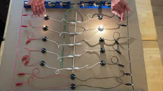
Now, the fun begins: finding the loose neutral. Carry on. I plug in a light with an extension cord, so I always see the lamp. First, I start thumping outlets with the palm of my hand. If the light flickers, I have found the culprit. It only sometimes works, but it is a good starting point.
Be nice to see what the wires looked like causing the issue. Not just a analysis of the outlet with the meters
Noted for future reference. Thanks for the feedback.
Steve, great video as always. Love the simplicity of using a nightlight to place a load on the circuit. Couple questions, if I may?
You mentioned that, in case of loose/floating neutrals neutral would assume line potential. This was demonstrated by your measuring potential at neutral wrt ground using the VAC function on your meter. Does this not also imply some capacitive coupling between line & neutral? How otherwise could neutral assume line potential?
In the case of capacitive coupling between line and neutral, I assume a dead short is prevented because a circuit with loose connections isn’t current-worthy?
I guess I just don’t quite understand how neutral would be “pulled up” to line potential due to a loose connection…
It's about relative impedance. The upstream loose connection on the neutral line was of very high impedance. The impedance of the 4 watt bulb was relatively very low. This represents a voltage divider with the impedance of the bulb in series with the upstream loose connection. In a voltage divider, the highest impedance has the greatest share of the 120v across it - causing the voltage difference between ground and the compromised neutral point to be close to line voltage - and the remaining voltage (a few volts) across the bulb.
Thanks for your reply. I can see how placing a load on the circuit creates a voltage divider in series with the HiZ loose connection. I simply don’t yet comprehend how any voltage is applied to the neutral conductor. I will continue to focus on this until I understand. Appreciate you, Sir!