Building an 868/915 MHz co-linear antenna for Lora TTN gateway

Vložit
- čas přidán 10. 09. 2024
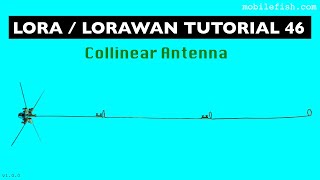
- In this tutorial we explain how to make an 868/915 MHz co-linear antenna for LoraWAN gateway with RAK831 and Raspberry Pi Zero W for The Things Network github.com/IRN....
Bending the wire for the co-linear 5.5dB antenna is likely the most challenging part and requires special care. Note that the frequency is tuned with the diameter of the loop and thus it must be made rather precisely. Design of the antenna is available in pdf Collinear 868 MHz LoRa antenna - github.com/IRN....
Institute IRNAS - irnas.eu/
Copyright © 2018 - This work is licensed under Creative Commons Attribution-ShareAlike 4 .0 Unported License


A picture explains more than a thousand words ever did. Thank you 🙏
Verry nice tutorrial, Easy to follow pleasant to watch.
Please explain how will you connect this antenna to your coax or to the transmitter , where is your ground plain?
Where do you come up with all the numbers used in the calculations?
Para 915MHz esta muy larga. Según mis cálculos debe estar entre 326 mm con una espiral a media longitud de diametro de 15mm. La longitud media de este tipo de antenas debe estar en 1/2 de la longitud de onda (163mm), la espiral de 15mm de diámetro y un segundo extremo de 163mm. En cambio las antenas dipolares se construyen a 1/4 de la longitud de onda con dos extremos sumando en total a 1/2 de la longitud de onda.
I have followed this procedure to the single word and put the antenna on a VNA (vector network analyser).
All I can say is that this antenna is the worse that the world has ever seen for lora 868 MHz.
Not the good frequency and not the corrrect impedance.
If you do not want to loose your time, do not follow this video.
Agreed. The loops are simply phasing/delays to preserve element-to-element phasing. Fixed loop dimensions seldom perform optimally. A better scheme is an adjustable linear phasing link, not a fixed loop. Also, the loop at the top is appropriate ONLY if another element were to be continued. It's presence in this design is undesirable and modifies the feed point impedance significantly (VNA verified).
Yeah. the size of the radiating elements are also wrong. I've seen a few youtube video's of people copying this design but they will have a far from optimal working antenna.
Great tutorial! Just wondering how precise you must be? Have you measured its performance?
Did you check VSWR? Did you check gain? Any data how it works on your Helium miner?
Is the wire diameter crucial, or something less could be good anyway? Thanks.
I put this antenna in a 3D simulation software. In terms of radiation patern, it is difficult to have a worse design as the radiation in the horizontal angle is almost 0 !! Max lob is at + and - 15° !!! :(
which just shows the failure of modelling software. I've used these antennas in the real world and they work really well
@@kimberlyolsen6384 It's funny given how much these are used that people seem to not understand that an antenna on a tower, shooting straight, misses the stations below it. I'm going to try this where I shoot up to a repeater on a ridge so the 15 deg lob seems pretty ideal!
@@DaveHojo Of course, I know that but be aware that you loose 3 db gain as there is a lobe at +15° and another one at -15°
Yep. Any antenna mounted above earth has a null in the horizontal plane. That is, any simulation will show that. Real earth is different - its finite conductivity lessens this effect. But the effect is still there. Fortunately it is possible to bring the shallowest-angle lobes closer to the horizon by mounting the antenna higher. Of course there are practical limits on height.
Great, how could this antenna design be modified to get 7-8 db?
Is the circumference of the loop a function of the wavelength? Thanks, Chuck
Is it ok to use solid copper electrical wire that's readily available in US hardware stores? And what about the diameter of the wire thickness? I'm planning to use 12AWG wire which 2.053mm in diameter. The next smaller diameter is 14AWG which 1.63mm.
too soft
I want to do this for lora 915mhz omini directional.I want to make a 4dbi antenna though can I make something like this but smaller to get the 4dbi at 915mhz?
Did you get the response spectrum of this kind of antenna and with this procediment of its construction?
What is the function of the top coil? Can I make the antenna out of unplated aluminium welding rod?
Thank You!!!
I need to install a long antenna on my 868Mhz device and swipe out the window.
I wanted to understand, if necessary, can I bend the antenna so that the device works from a long distance?
Did you say "thick welding wire with copper coating"? What I have is 14 AWG (1.72mm) wire and 15 AWG(1.58mm) wire. Can this be use, it bends quite a bit.
No, TIG wire. TIG welding wire. TIG filler rod.
Sir have u a measurement for uhf antena gime me for best uhf antena
Kje dobim tig žico 1.4mm z bakrom? :(
Nice and clear ;)
is a ground plane needed ?
Awsome... Tanks :)
Hello, on github the design for the 915 antenna have the link offline
Why are you making these antennas
@@scottscotts808 lol
Ø 28 (outer diameter) you 20mm
the top loop does nothing. The loops are to put all the half wave radiating parts into the same phase. The loop has to be half a wave length long. At 868MHZ that's 17cm so the diameter is 55mm I never saw a thumb being 55mm wide. The impedance of a half wave radiator is thousands of ohms. so you cannot connect a half wave radiator onto a SMA connector, you need an impedance transformer. Just look at a J-Pole antenna and forget this dumb video.